
Generator set fuel line sizing fixes the bore of the suction and return pipes from the flow the engine needs, the velocity the fuel may reach, and the pressure drop the lift pump can afford. Tesla Power shows how to calculate all three for a 200kVA set, then states the bore on the drawing before a supplier quotes.
- Flow follows the rating: a 200kVA set at 160kW burns about 34 L/h at full load.
- Suction velocity stays under 0.5 m/s and return under 1 m/s, which at this flow is a small bore.
- Pressure drop over a long run, not velocity, decides the size on most plant rooms.
- Put the route and the lift on the enquiry, and the frames in the export frame range are quoted with the right connections.
What does fuel line sizing decide before the pipe is bought?
It decides four things: the bore of the suction line, the bore of the return, the height the lift pump can draw from, and whether the set needs a day tank. All four follow from the flow figure, and the flow figure follows from the rating rather than from the pipe. A line chosen by eye is usually oversized on a small set and undersized on a long run. Tesla Power writes the figure into the offer line so the basis travels with it.
The cost of getting it wrong lands on the engine rather than on the pipe. A suction line that is too small starves the injection pump at full load, and the symptom is a set that hunts under load and clears when the load drops. A return line that is too small raises the fuel temperature in the tank, and a hot tank loses density and lubricity together.
How is the flow rate worked out from the rating?
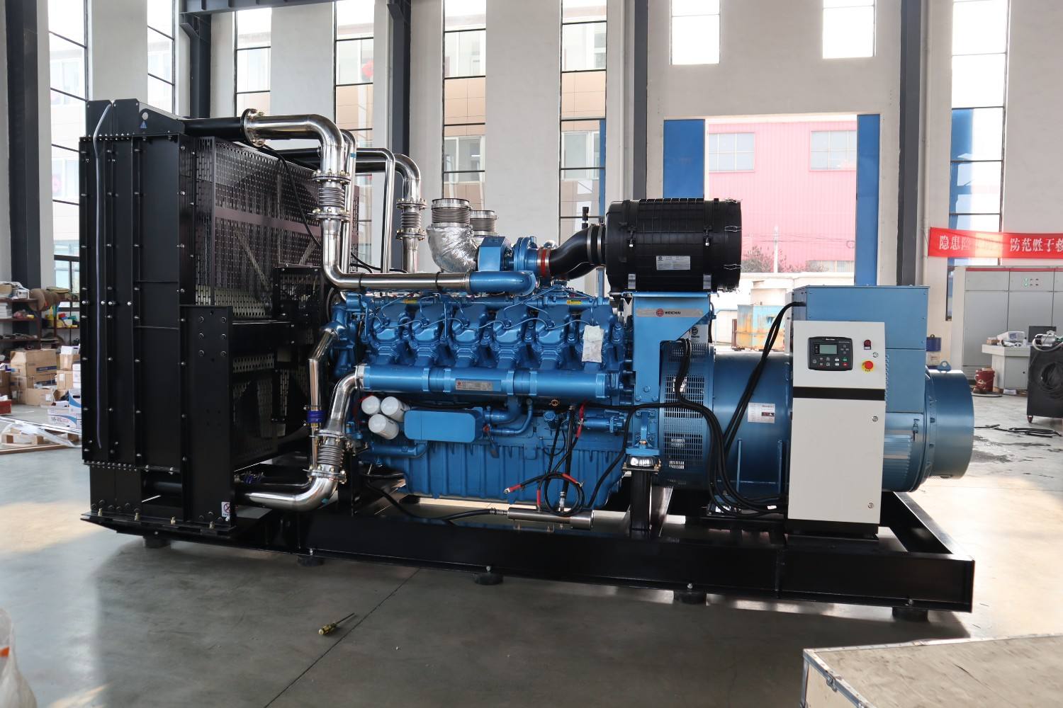
Take the engine's specific fuel consumption and multiply by the load. A 200kVA frame at 0.8 power factor carries 160kW, and a typical 0.21 L/kWh gives 160 × 0.21 = 33.6 L/h at full load. Add the return flow, which on a common rail engine is 2-4 times the burn, and the suction line has to pass the burn plus the spill.
Size for the pump, not for the burn. A lift pump rated at 120 L/h with a 34 L/h burn returns most of what it draws, so the suction line carries 120 L/h while the engine burns 34 L/h. That factor of three is the number most site drawings miss, and it is the reason a line sized on burn alone runs hot on a long return. Most generator manufacturers publish the pump curve and leave the line loss to the installer.
Which velocity applies to the suction and the return?
The suction side is held to 0.5 m/s and the return to 1.0 m/s. The suction limit is tighter because a low pressure in the line releases dissolved air, and bubbles reaching the injection pump cause a misfire that no filter will fix. The return limit is looser because the line is under slight pressure and bubbles travel with the flow rather than gathering at a high point.
Run the arithmetic and the limits turn out to be generous at this rating. A 200kVA set drawing 120 L/h through a DN15 line with a 16mm bore gives a velocity of 0.17 m/s. The same flow through a DN10 line gives 0.66 m/s, which is over the suction limit, so DN10 is the first size that fails and DN15 is the first that passes. Yangzhou Tesla Power states the ambient and the altitude beside the rating.
| Line | Bore | Velocity at 120 L/h | Against the limit |
|---|---|---|---|
| Suction, DN10 | 8mm | 0.66 m/s | Over 0.5 m/s |
| Suction, DN15 | 16mm | 0.17 m/s | Passes |
| Return, DN10 | 8mm | 0.66 m/s | Passes 1.0 m/s |
| Return, DN15 | 16mm | 0.17 m/s | Passes |
What pressure drop does a 40m run produce?
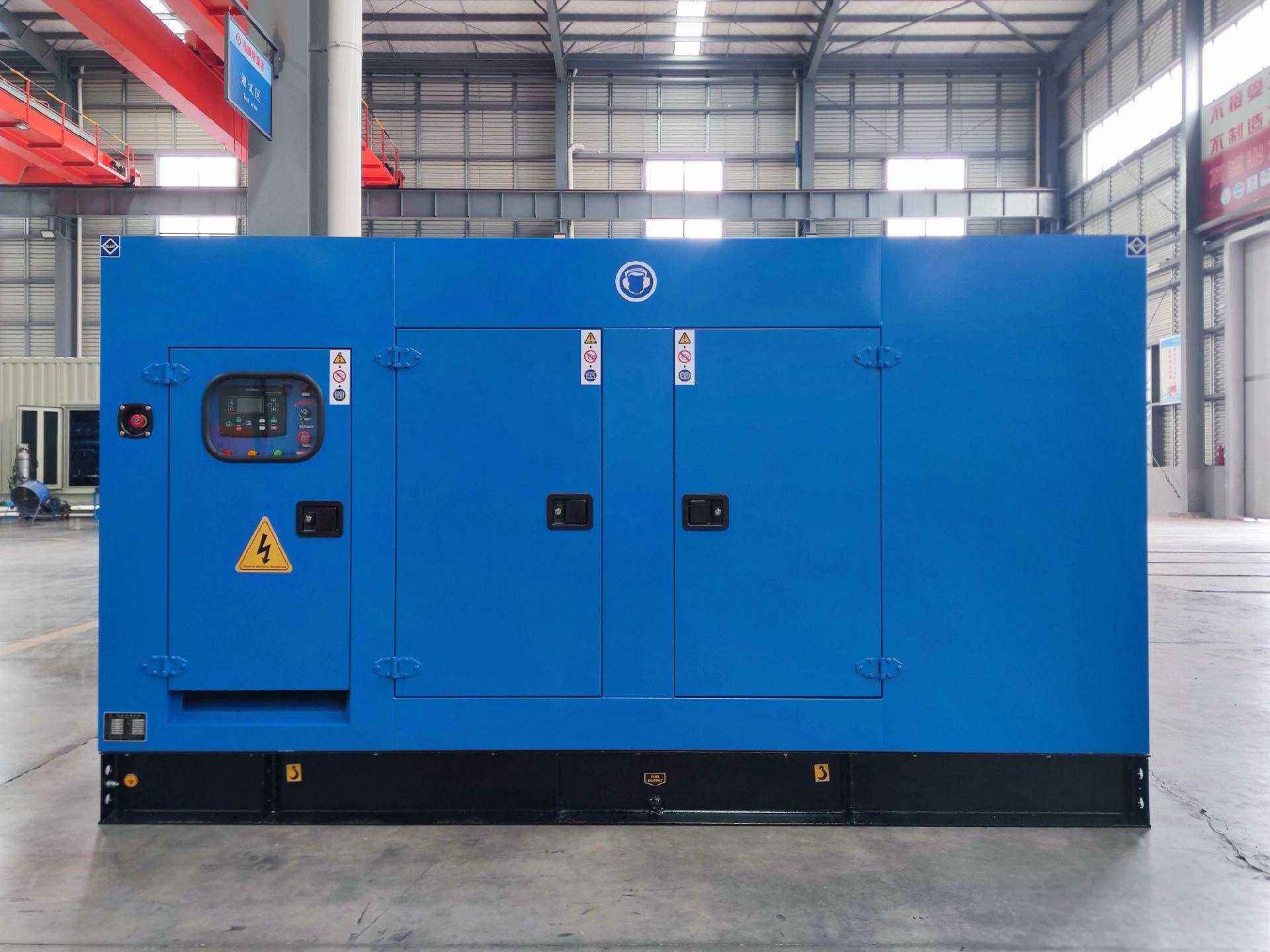
Use the Darcy relation with the laminar friction factor, because fuel at these flows is slow enough to stay laminar, on the reference conditions in the ISO 3046-1 fuel consumption basis. At 120 L/h through DN15 over 40m the drop is about 12 kPa, which is 0.12 bar. The same flow through DN10 over the same run gives about 190 kPa, and that figure is more than most lift pumps will pull.
Put the two results beside the pump curve. A lift pump that delivers 120 L/h at 0.3 bar free flow cannot also pull 1.9 bar of friction, so the DN10 line throttles the flow and the engine starves at full load. The DN15 line leaves 0.28 bar of the pump's capability for the lift, which is enough for a tank 2m below the engine. Chinese generator suppliers often quote a bore without asking for the run length, which is how a 40m circuit ends up with a 10m drawing.
Where does the suction lift set the limit?
The lift is measured from the fuel level, not from the tank bottom, and it is the figure that fails first on a buried tank. A lift pump draws by creating a partial vacuum, and diesel at 20°C begins to release vapour at about 0.6 bar below atmospheric. That caps the theoretical lift near 6m and the practical lift near 2m once the line loss and the filter are counted. Tesla Power reads that figure on the site sheet before the plate is printed.
A tank 4m below the engine therefore needs a transfer pump or a day tank rather than a bigger suction pipe. A bigger pipe lowers the friction but cannot lower the lift, and the vapour release happens at the pump inlet whatever the bore. That distinction is the one a site team usually gets wrong when the set starves after a tank relocation. A generator for a bulk tank therefore needs the lift written on the drawing rather than assumed.
How does cold fuel change the answer?
Viscosity rises sharply as fuel cools, and friction rises with it. Diesel at 3 cSt at 20°C reaches about 8 cSt at 0°C, and the pressure drop in a laminar line scales with viscosity, so the same 40m run costs 2.7 times as much at 0°C. A line that passes at 12 kPa in summer reads 32 kPa in winter.
A return line that keeps warm spill flowing back to the tank raises the tank temperature over a long run, and a tank inside a plant room holds 10-15°C above the yard. Where the tank sits outside, the line bore goes up one size and the trace heater question comes onto the drawing. A generator for standby duty keeps the run short enough that cold fuel costs nothing.
Which fittings cause most of the loss?
Elbows and strainers cause more loss than the straight pipe on a short run. A 90° elbow carries the equivalent of 30 diameters of straight pipe, so six elbows in DN15 add 2.9m to a 10m run. A suction strainer adds more again, and a blocked strainer is the most common cause of a set that starves after a year of service.
Count the fittings before choosing the bore, and put a vacuum gauge on the suction side of the strainer. A reading above 0.2 bar means the strainer is loading, and the gauge is the cheapest instrument on the fuel circuit. Most suppliers offer the gauge as an option, and it belongs in the standard build on an export set. A generator in a cold store needs the gauge and the trace together, because the two faults look alike on the controller.
What does the factory check on the fuel circuit?
Our test bay runs the set at full load for two hours with the fuel drawn from a tank at the height the site will use, and records the suction vacuum at the strainer. The same run is done on the 200kW frame on the WP10 block before the line sizes are fixed for the order. A set that reads above 0.15 bar on a clean strainer has a line that is too small or too long, and the fix belongs at the factory rather than on site.
The test also checks the return temperature. A return that reads more than 10°C above the tank temperature means the spill is being heated and the tank will climb through a long run. Tesla Power Equipment records both figures on the test sheet, and they travel with the set beside the fuel curve.
How should the enquiry state the fuel route?
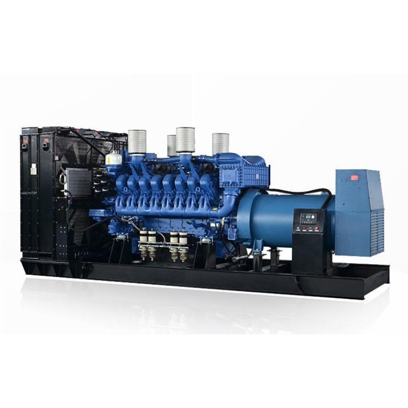
State five items: the tank capacity, the height of the lowest fuel level below the engine, the horizontal run in metres, the number of elbows, and whether the tank sits inside or outside. Those five decide the bore and the pump, and a supplier who has them can draw the circuit rather than guess at it. The same frame appears in the 500kVA silent set with the ATS option, where the plate states the same basis.
Send the five with the load list to the export desk, and the reply carries the line sizes, the lift, and the strainer position on a sketch. The site planning notes carry the same five items as a form, and Tesla Power sends it with every quotation so two offers arrive with the same route drawn.
What is recorded at handover?
Three readings go on the handover sheet: the suction vacuum at full load, the return temperature, and the tank level at the start and end of the run. The factory and the test bay keep the sheet in the order folder. The three together prove the circuit holds the rating, and they give a service engineer a baseline for the next visit. A vacuum that has climbed 0.1 bar in a year points at the strainer rather than at the pump.
Record the bore and the material on the same sheet. A line replaced later with a smaller bore is a common cause of a set that starves after a maintenance visit, and the record is what catches it. A genset for a bulk tank with a buried line carries that note in the file, since the line is the part nobody can see. The monthly test in the NFPA 110 routine is where a rising vacuum reading is caught first. Tesla Power keeps the reading beside the load record rather than in a covering letter.
Frequently asked questions about generator set fuel line sizing
DN15 is the practical minimum on most sets up to 500kVA, whatever the velocity figure says. A smaller bore passes the flow and blocks more easily, and the fittings for DN10 are harder to find on site. The velocity check confirms DN15 rather than selecting it.
It can be smaller, because the return limit is 1.0 m/s rather than 0.5 m/s. In practice the two lines are often the same bore for simplicity, and the return is the one that runs hotter. Keep the return below the fuel level so it cannot aerate the tank.
It can, and it should at the engine connection, where vibration would crack a rigid line. Keep the flexible section short and rated for diesel, and support it so it does not sag into a trap. A sagging hose collects water and air at the low point.
Because the flow is highest there and the line loss rises with the square of the flow. A line that passes at half load can fail at full load with no other symptom. The vacuum gauge at the strainer shows the problem before the engine does.
It removes the lift problem and leaves the bore problem, since the line from the day tank is short. A day tank holds 4-8 hours of fuel and sits above the engine, which is why it is the usual answer on a buried main tank.
Solid-drawn steel with a painted outer surface for the main run, and a diesel-rated elastomer for the flexible section. Copper is common and reacts with sulphur in some fuels. Plastic is not acceptable on the suction side of a diesel engine.
At every service interval, and at the first service after commissioning. A new tank sheds mill scale for a year, so the first clean matters more than the rest. Record the vacuum reading before and after, and the trend tells you whether the tank is the source.
The generator set CE marking requirements sit in the technical file, and the fuel circuit drawing is part of that file rather than part of the declaration. Conformity assessment for the assembly checks that the drawing and the build agree. A buyer reads the drawing against the set at handover, and Tesla Power files both together.