
Generator set voltage droop is the controlled frequency fall that lets two or more diesel generator sets share load without fighting each other. This guide explains how droop control works, the limits ISO 8528-5 sets, and the commissioning steps a buyer should verify before accepting a paralleling package. Use the explanation to compare supplier quotations and request a scoped quote that names the droop setting, the governor type and the test evidence. Tesla Power sizes droop and isochronous modes for export projects, and the same record backs every handover we issue. Three facts decide the outcome. First, droop is a percentage of rated speed, not a fault. Second, a 5% droop band means the set drops 5% of its speed from no load to full load. Third, the setting must match the other machines on the bus, or load will not divide evenly. A set that drifts out of band trips on load step or refuses to pick up its share. Read the paragraphs below before you freeze the specification, and ask our industrial standby diesel generator set team for the governor curve in writing.
- Confirm the droop percentage and the governor type before you sign the purchase order.
- Ask for the load-share test report, not only the factory acceptance certificate.
- Match the droop band to the other sets already on the bus.
- Keep the commissioning curve with the project file for the next service visit.
What is generator set voltage droop on a diesel set?
Droop is a deliberate, linear relationship built into the governor. As the load on the set rises, the governor lets the speed fall by a fixed percentage of the rated value, and the alternator voltage follows the speed through its regulation. The fall is not a fault; it is the signal that tells the set how much load it should carry relative to its neighbour. A 500kW set on a 5% droop band runs at 50Hz with no load and about 47.5Hz at full load. The next set on the same bus does the same, so both fall together and share the load by their rating. Our help and advice pages show the governor display where the band is set.
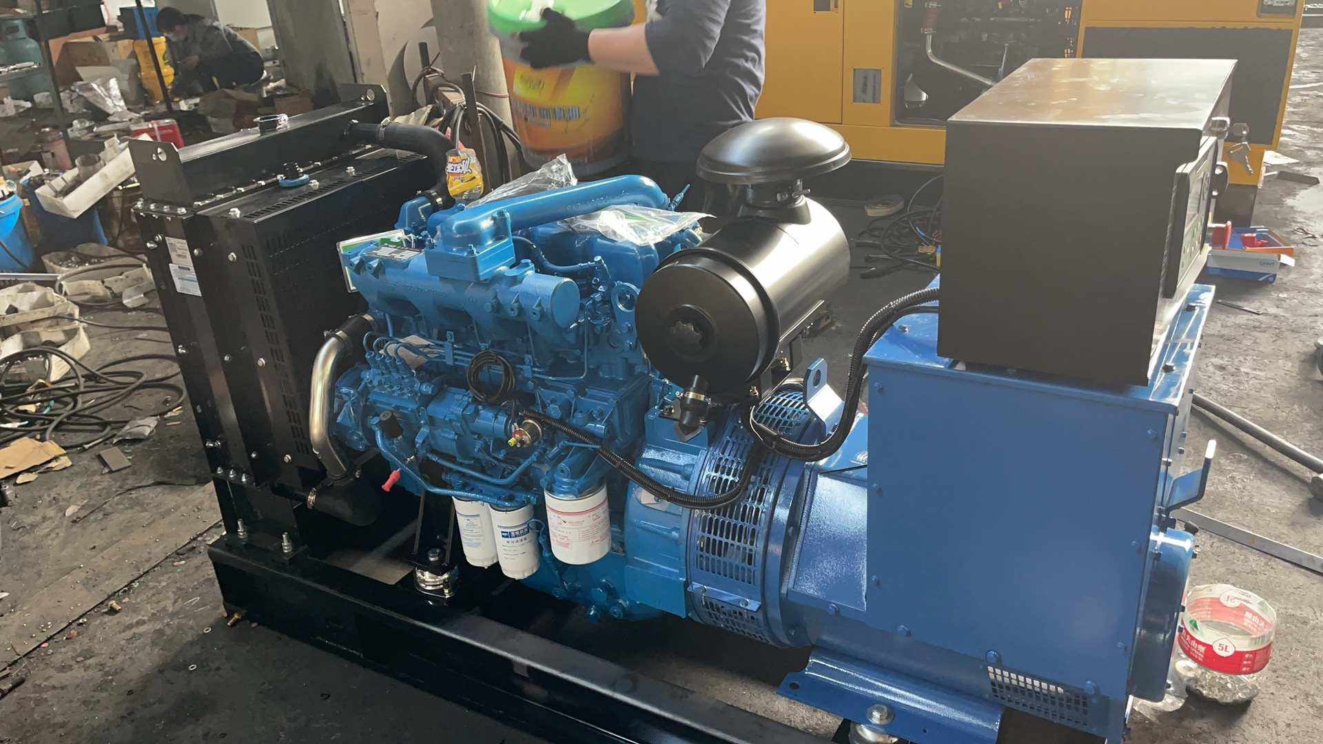
The alternative to droop is isochronous control, which holds speed exactly at 50Hz regardless of load. A single islanded set can run isochronous. Two isochronous sets on one bus will both try to hold 50Hz and will instead hunt, because neither gives way. Droop is the simple rule that lets the machines cooperate. Tesla Power selects the mode from the single-line diagram and the site load study before the panel is wired.
Why do paralleled sets use droop control?
Parallel sets must divide load. Droop gives each set a shared reference: the bus frequency. When total load rises, the bus frequency falls and every governor adds fuel in step with its own band. A 1000kW set carries twice what a 500kW set carries, because its band spans the same frequency drop over twice the power. Without that shared reference the sets cannot agree on who carries what. The fall is small, but it is what makes the sharing stable.
Droop also removes the need for a fast communications link between the governors. Each set reads only the bus frequency, which it can measure at its own terminals. That keeps the system simple and keeps a failed data cable from taking the whole plant down. For a remote site this matters more than it sounds. The equipment supplier's profile lists the control platforms built for export duty; see our build record.
What droop value does ISO 8528-5 allow?
ISO 8528-5 defines the steady-state and transient behaviour of paralleled generating sets and sets the droop band as a percentage of rated speed. Most land-based sets use a 3% to 5% droop band; 5% is the common default for equal load sharing, while 3% gives a stiffer bus at the cost of tighter tolerance on the setting. The standard also limits the steady-state speed band and the recovery time after a step load. A set that leaves the factory at 4.8% must stay inside the stated tolerance across its life, because the neighbour on the bus assumes that value. Tesla Power quotes the droop band on every offer and the test tolerance beside it, so the buyer can check the report against the same numbers. The table below lists the figures a buyer should see on the test report.
| Parameter | Nominal | Acceptance limit | Reference |
|---|---|---|---|
| Droop band | 5% of rated speed | 4.5% to 5.5% | ISO 8528-5 |
| Steady-state speed band | 50Hz | Within 1.0Hz | ISO 8528-5 |
| Voltage regulation | 400V | Within 2.5% | IEC 60034 |
| Recovery after step | Full load step | Under 5s | NFPA 110 |
Droop band versus steady-state tolerance. A wider band tolerates more setting error between sets, which is why 5% is the export default for equal load sharing across a paralleling bus. A 3% band needs the two governors to agree within a tighter window, or the load divides unevenly and one set runs hot under a real demand step. Buyers should read the band from the test sheet, not trust the nameplate figure printed at the factory gate.
Generator set voltage droop ce marking requirements name the band the set was checked against, so the next service engineer can repeat the test on site. The ISO 8528-5 standard gives the full test sequence and the permitted tolerances for each rating class, and it is the reference most export buyers ask for before sign-off. A documented band also protects the warranty, because it proves the set was set correctly when the commissioning sheet was signed.
How does droop govern load sharing?
The bus frequency is the only signal the governors need. When load increases, frequency dips, and each governor opens its fuel rack in proportion to its own band. A larger set has a larger band in absolute power, so it picks up more of the new load. The result is stable division without any master controller telling each set what to do. Tesla Power Equipment documents the droop and isochronous settings on the same single-line diagram so the values cannot drift apart between sets built in different weeks.
Worked load-share example at 500kW. Take two 500kW sets rated for 1000kW of total bus capacity, each on a 5% droop band, feeding an 800kW site load. Each set carries half the load, so the share per set is 400kW = 800kW / 2. The frequency drop per set is 5% of 50Hz = 2.5Hz, so the bus settles at 47.5Hz = 50Hz - 2.5Hz at full load. If one set were set to 3% by mistake, it would carry less and the 5% set would overload, because the 3% machine would need a larger frequency drop to add the same power. The equation shows why the bands must match before paralleling.
The same arithmetic scales to mixed sizes. A 1000kW set and a 500kW set on equal 5% bands share demand in a 2:1 ratio, so the larger set carries 500kW and the smaller carries 250kW. The percentages stay equal even when the absolute powers differ. Our note on genset voltage sag explains what happens to the bus when a step load arrives faster than the governors can respond.
When buyers compare generator set voltage droop manufacturers, the load-share report matters more than the nameplate, and china generator set voltage droop suppliers often quote a 5% band as the export default. The same arithmetic scales to mixed sizes, which is how generator set voltage droop for industrial site duty is set when a 1000kW set runs with a 500kW set, and generator set voltage droop in export projects follows the same 2:1 ratio rule. Conformity assessment for the parallel set starts with the band check, because the whole package depends on it.
Which field readings show droop is set wrong?
The clearest sign is uneven load division at steady state. If two equal sets show 60% and 40% load at a flat 800kW demand, the bands do not match, and the lighter set is holding the bus while the heavier one drifts. A second sign is a bus frequency that sits outside the 1Hz steady-state band, which points to a band set too wide or a governor with excess deadband. A third sign is a set that picks up load only after its neighbour is already near full, which means its band is too shallow. Tesla Power sees this fault most often on buses where the bands were set by two different technicians without a shared worksheet.
A voltage that sags but does not recover
A voltage that sags but does not recover within five seconds is not, and it usually means the AVR or the excitation system is not following the governor. The droop band governs speed, but the alternator must hold voltage while speed settles, or the load will see a double dip. Log the recovery trace during commissioning so a future fault can be compared against a known good run. The single-phase alternator page shows the regulation class we specify for small sets.
Read the governor display during a staged load step rather than trusting the nameplate. A set that looks correct at no load can still divide badly under real load, because droop only acts when the set is actually carrying load. The reading at 25%, 50% and 100% tells the true story and confirms whether both bands were set to the same value.
How do you set the droop potentiometer at commissioning?
Setting the band is a measured procedure, not a guess. Run the set on the bus with a known load, read the no-load frequency, then read the full-load frequency, and adjust the potentiometer until the drop equals the target percentage of rated speed. Record both readings on the commissioning sheet beside the set serial number. Repeat on every set that will share the bus, because the bus only behaves if the bands agree. Yangzhou Tesla Power logs the potentiometer position for each set so a later service visit can return to the exact value.
Step-by-step commissioning sequence
First isolate the bus and run the set at no load to confirm the base frequency. Second apply a stepped load to 100% and record the settled frequency. Third compute the percentage drop and compare it with the target band. Fourth adjust the potentiometer and repeat the step until the reading lands inside tolerance. Fifth repeat the whole sequence on the second set. Sixth confirm both sets divide an 800kW load within 5% of their rated ratio before you sign the report. A short cool-down follows each run to protect the turbocharger.
Do not rely on the factory default alone. Transport, temperature and panel variation move the band enough to matter on a tight bus. The five-minute check at the factory gate does not prove the set will share on site. Apply a 100% step and time the recovery against the NFPA 110 limit, then request a scoped quote from our engineering team for the commissioning worksheet we use on export projects and ask for the curve as a signed PDF.
What is the difference between droop and isochronous control?
Droop lets frequency fall with load so sets can share; isochronous holds frequency fixed so a single set can serve a sensitive load. The two modes solve different problems, and mixing them on one bus is the usual cause of hunting. A site that runs one set most of the time and adds a second only for peak load can run the base set isochronous and the second set droop, with a transfer rule that prevents both from holding the bus at once. The choice is a design decision, not a setting you change on site. Tesla Power documents the mode in the single-line diagram so the operator cannot mix them by accident.
When isochronous is the right choice. Use isochronous for a single islanded set that feeds computers, medical gear or a precise process where a 2.5Hz swing would disturb the load. Use droop the moment a second set can be paralleled, because only droop gives stable sharing without a communications link. Some controllers offer a soft transition that drops the set into droop the instant another machine closes onto the bus. That transition must be tested, not assumed, during commissioning.
Use droop the moment a second set can be paralleled, because only droop gives stable sharing without a communications link. This is why generator set voltage droop for data centre sites keeps two sets sharing the bus even when the building load swings with the cooling plant. The bus frequency is the only reference the governors need, so the rule holds from two sets to ten.
Site acceptance checks for droop control
Acceptance is a short list repeated on every set. Confirm the band value, confirm the load division, confirm the recovery time, and confirm the report carries the serial numbers. A buyer who checks these four items before sign-off avoids the most common paralleling complaint, which is uneven load share that only appears under real demand. The checks take an hour with a load bank and a frequency meter, and they protect the warranty by proving the set was set correctly at handover. Keep the signed sheet with the generator serial number in the file name.
Acceptance checklist before sign-off. Measure no-load frequency and full-load frequency on each set. Compute the droop percentage and compare it with the stated band. Apply a 100% step and time the recovery against the NFPA 110 limit. Paralleled two equal sets and confirm the 800kW load divides within 5% of the rated ratio. File the curve with the project. These five steps turn a vague handover into evidence the next engineer can repeat. Generator set voltage droop for data centres follows the same list, with a longer hold at full load to reflect continuous duty.
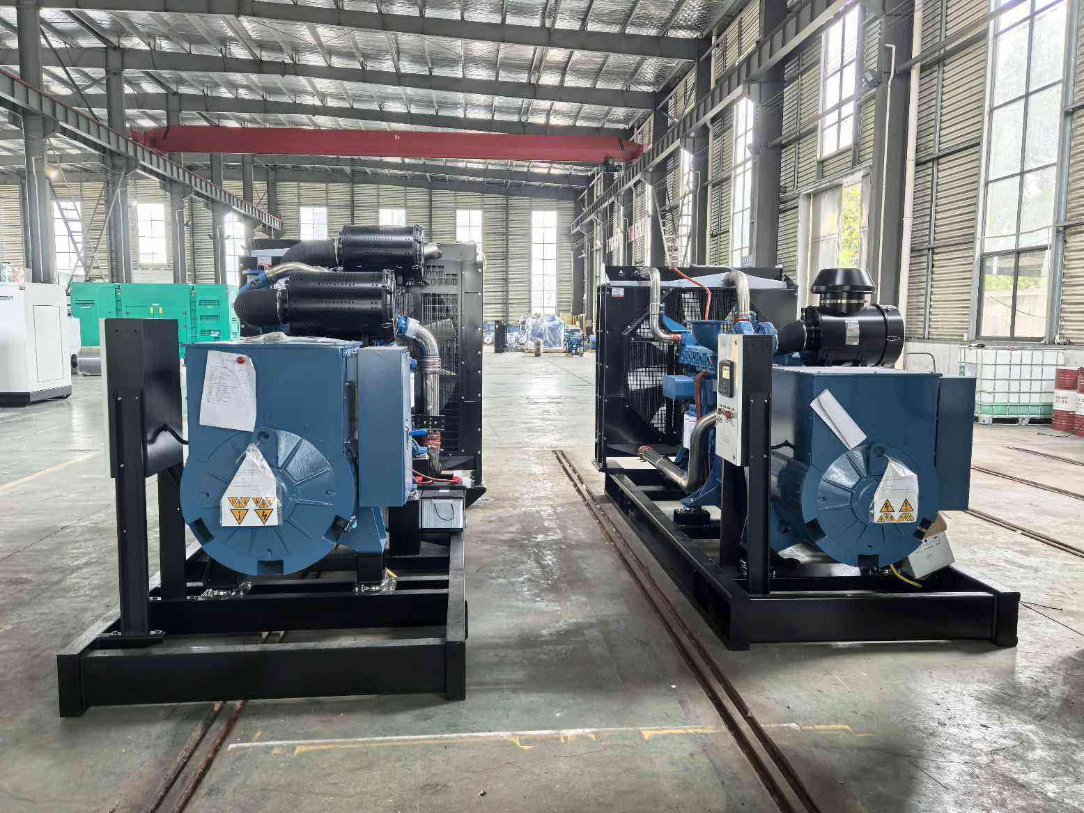
Note the ambient temperature on the report. A hot commissioning day changes the engine response and can move the recovered frequency by a fraction of a hertz. The datasheet states the correction, and the report should note where the site sits on that curve so a cold-day retest is read correctly. Our project news page carries field reports from paralleling jobs in hot climates. For the alternator regulation class, see IEC 60034, which we cite on every test sheet.
Frequently asked questions about generator set voltage droop
Use 5% unless the project specifies otherwise. The 5% band tolerates small setting differences between sets, which keeps load sharing stable without a master controller. A 3% band is acceptable when every governor is set and verified to a tighter tolerance. State the value in the enquiry so the factory sets all sets to the same figure before they leave the line.
Not on the same bus at the same time, because both will try to control frequency and the bus will hunt. The usual design runs the base set isochronous and brings a droop set online only when needed, with a transfer rule that prevents overlap. Test the transition during commissioning rather than assuming the controller handles it.
Droop only changes frequency by a few hertz across the load range; it does not distort voltage or waveform. Voltage is held by the alternator regulator while the governor manages speed. A 2.5Hz swing at full load is normal and well within the tolerance most loads accept. Sensitive loads should size the set so they sit in the upper part of the band.
Read the no-load frequency, then the full-load frequency, and divide the difference by the rated frequency. A 500kW set at 50Hz that falls to 47.5Hz shows a 5% droop band. Repeat the reading on each set that shares the bus, and compare the values before you accept the package. The measurement needs only a frequency meter and a staged load.
Uneven division usually means the droop bands do not match. One set holds the bus while the other carries too little, and the heavier set runs hot. Re-measure both bands and adjust the one that is off. Check also for a stuck potentiometer or a governor with excess deadband, because either fault mimics a wrong band setting.
No. A single islanded set can run isochronous and hold 50Hz exactly, which suits a sensitive load better than droop. Add droop only when a second set can be paralleled, because only droop gives stable sharing without a communications link between the governors. The mode is a design choice fixed in the single-line diagram.
Record the no-load and full-load frequency of every set, the computed droop percentage, the recovery time after a full step, and the serial numbers. Add the ambient temperature and the load step plan. Tesla Power issues this sheet as a signed PDF so the next service engineer can repeat the test and confirm the set still shares load as designed.