
A genset earthing method fixes where the neutral link sits and which path clears a fault. Tesla Power Equipment sets out the four systems below, then lists the readings to record on site, so a quotation names the link state rather than leaving the choice to an installer.
- Neutral link state, because a link in the wrong place leaves the fault path open and the breaker trips on nothing.
- Electrode resistance, since a dry season lifts it and stretches the disconnection time at the far end of a feeder.
- Parallel operation, where two links turn a single set rule into a circulating current path.
- The record that proves each reading, kept with the frames we build for export.
What does a genset earthing method decide for a site?
It settles three things that a price sheet leaves out. The first is the path a fault current takes. The second is the device that clears it. The third is the touch voltage a person meets when a live part fails. A link in the wrong place does not make a set unsafe on its own. It makes a fault invisible when one occurs, and the first sign is a panel that bites.
Take a 400kVA frame at 400V and 0.8 power factor, carrying 320kW. Through a 10Ω rod the loop is 11Ω, so 230 ÷ 11 = 21A and no breaker moves. Through a bonded star point the same fault draws 250A and a 630A breaker clears it inside 0.4s. The same set, two outcomes, and only one of them is protection. The figure belongs on the offer sheet beside the rating, where a buyer can read it against the site conditions.
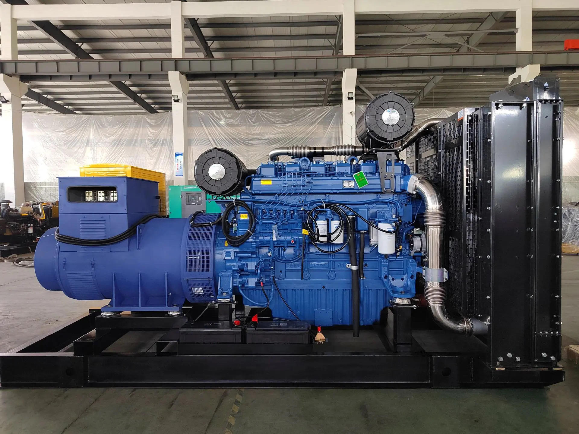
How do TN-S, TN-C-S, TT and IT differ at the set?
The four differ in one respect, which is whether the fault return is a conductor in the supply cable or the ground itself. TN-S keeps a separate protective conductor from the transformer to the load. TN-C-S combines neutral and protective duties upstream and splits them at the origin. TT relies on a local electrode. IT runs isolated, or through a high impedance.
The table sets the four against the link state each one needs. The two families behave differently at the far end of a feeder, so the second family needs a different test rather than a different setting. Tesla Power marks the family on the drawing, because a set bonded for the wrong one of the four clears nothing at all.
| System | Fault return path | Neutral link at the set | What the site checks |
|---|---|---|---|
| TN-S | Separate protective conductor in the supply | Removed, one bond upstream | Continuity of the protective core to the origin |
| TN-C-S | Combined, then split at the origin | Removed, bond at the split point | That no second bond is fitted at the board |
| TT | Ground through a local electrode | Fitted, at the star point | Electrode resistance and the trip time under test |
| IT | Isolated, or high impedance to earth | Fitted only through the impedance | Insulation monitoring and the first fault alarm |
Where does the neutral bond belong on an export set?
On a set that runs as a standalone source, the bond belongs at the alternator star point, and it belongs there once. One point gives the installation a reference, lets a line to earth fault draw current, and holds the protective conductor near earth potential while the set carries load. That is the arrangement most genset manufacturers ship on a standby build.
Two bonds, one at the set and one at the board, push neutral current onto the frame. That current returns through the skid, the foundation steel and any parallel pipe, and it heats a link that carries no load current by design. A clamp reading on the link shows it before the paint blisters, and the reading belongs on the commissioning sheet.
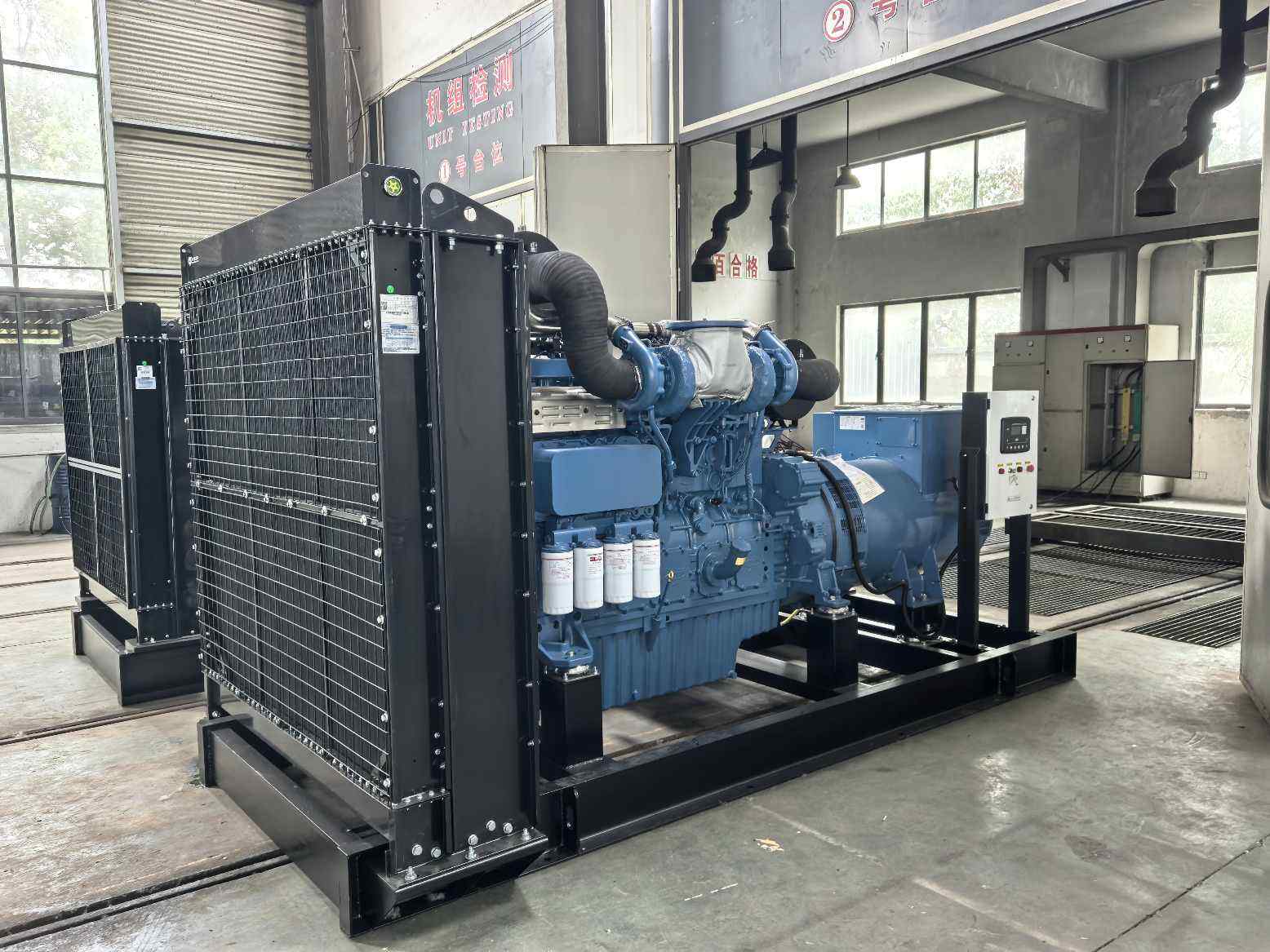
What changes when two sets run in parallel?
Two sets in parallel need one bond between them, not two. Where each set keeps its own link, the two star points sit at slightly different potentials, and the difference drives a current through frames, skids and protective conductors. The current is small at light load and grows with unbalance. It hides during commissioning and shows up a year later.
The usual arrangement bonds the first set and isolates the neutral of the second, with the link accessible and labelled. A changeover or a maintenance isolation then has to leave that bond alone. Losing it during a transfer leaves the board unearthed while the second set runs, and a fault then has no path at all. Chinese genset suppliers rarely label the link, and the omission costs an hour at handover. A site that records the reading each month sees the change before it reaches the trip point on the controller.
How does a TT installation clear a fault without a metallic path?
It clears through the soil, and soil is a poor conductor. Take a 400kVA set on a TT board with a 10Ω electrode and a 230V line to neutral fault. The loop is 10Ω plus the set's own 1Ω, so 230 ÷ 11 = 21A. That current will not trip a 630A breaker in any useful time. The frame rises to 210V, and the set keeps running.
That is why genset earthing for a plant room with a TT board needs both a device and a rod, not one or the other. The device limits how long a shock lasts. The rod limits the touch voltage during it. A 10Ω rod holds the frame near 210V for the trip time, which is survivable and still not a safe touch. Yangzhou Tesla Power records both figures on the same sheet.
Which checks prove the electrode is still sound?
Three checks answer three different questions. Fall of potential gives the resistance of the rod alone and ignores parallel paths through building steel. Loop impedance gives the path a fault would actually take, including every parallel bond. Continuity proves the conductor between rod and bar is still connected, and paint is the fourth check that most crews skip.
The three do not agree, and that is the point. A rod measured at 4Ω on its own can sit in a loop of 0.9Ω because a water pipe and a steel frame carry most of the current. The loop reading flatters the installation until the pipe is replaced with plastic. Then the same fault finds 21A instead of 250A.
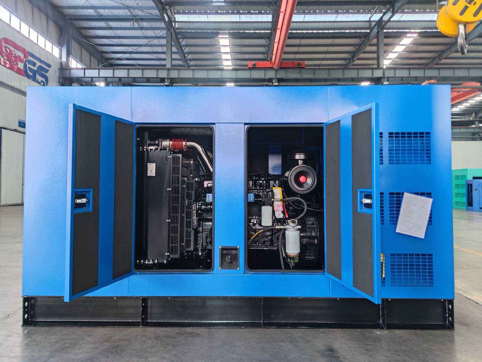
Where do earthing schemes fail on container builds?
A container build adds two failure modes. The enclosure becomes the protective conductor, so every panel bolted to it joins the path through a painted seam. The container also sits on corner isolators for transport, which means the structure is insulated from the ground it appears to touch. Both faults pass a visual inspection and fail a loop test.
Both are cured at build, and genset earthing for the container starts at the drawing rather than at the site. A dedicated protective bar inside the box carries the fault, and a braided bond from that bar to the base frame gives the enclosure a path that does not rely on a bolted panel. The 400kW frame on the Weichai WP13 platform carries that bar as standard. The same reasoning applies to the second frame, which carries the correction on its own plate rather than in a note.
How is the parallel bond proved at handover?
Prove it with both sets running and load shared, not with the plant dead. A continuity test on a dead board proves a conductor exists. A clamp reading on each link at 60% load proves the current that actually flows, and the figure on the isolated neutral should sit near zero. Ten minutes of load tells a truer story than an hour of resistance readings.
Then trip one set and watch the other. Bond current should stay near zero and the protective conductor should stay at earth potential. A reading that jumps when the second set takes load means two links are fitted. The fix is a link rather than a setting, and Tesla Power Equipment writes the result into the commissioning file for the site crew. The reference condition is defined in the NFPA 110 emergency power rules, which names the tolerance and the test point.
What should the handover record carry?
Four figures and one photo. Electrode resistance, loop impedance at the furthest board, bond continuity, and the device trip time, each with the instrument named and the weather noted. The photo shows the link and its label, and it settles any later argument about what was fitted on the day. The same frame appears in the 120kW set on the WP6 platform, where the plate states the same basis.
The file should carry the link state as a written word, fitted or removed, rather than a tick. A tick tells the next reader nothing, and a link nobody can describe is a link the next contractor changes. The 500kVA silent set with the ATS option ships with that line filled in.
Which questions come up before an export order?
Four questions decide the build on a set for standby duty. Which system does the board use? Is the set the only source, or does it parallel with mains? Is there a second set? Where does the site rod land? Each answer changes a wire or a link, and none of them changes the alternator rating. The same frame appears in the 1000kW container build for standby duty, where the plate states the same basis.
The answers belong in writing before the order, because a set cannot be reconfigured at the port. The site planning notes set out the readings a buyer should send, and the ISO 8528-1 rating classes fix the duty class that goes on the plate. The genset CE marking requirements belong in the technical file beside that sheet. Tesla Power reads that figure on the site sheet before the plate is printed.
Frequently asked questions about genset earthing method
Inside the terminal box on a standalone set, because the link then travels with the machine and cannot be left out at site. A panel bond works on a single installation with one set. It fails when a second set arrives and nobody rechecks the link.
The frame is a bond path, not an electrode. It carries fault current between terminal box and earth bar and does nothing to lower resistance to soil. A skid on a slab with a plastic membrane has no path until a rod is driven. Tesla Power reads that figure on the site sheet before the plate is printed.
Below 10Ω where the soil allows it, and below 30Ω as a working limit in dry ground. The figure that matters is loop impedance with every parallel path included, because disconnection time is calculated from that number rather than from the rod alone.
No. The device limits how long a shock lasts and the electrode limits touch voltage during it. A site with a 200Ω rod and a 30mA device still holds the frame near 180V for the trip time, which is a shock rather than a fatal one, and not a safe touch. Tesla Power reads that figure on the site sheet before the plate is printed.
Once a year, and once after any excavation near the rod. A new driveway, a drainage trench or a replaced water main all change the parallel paths, and loop impedance moves with them. Record the season beside the figure.
The link arrangement does not change with the duty class. What changes is the fault current the link has to survive, because a prime set runs at full load for longer and the alternator heats. Size the link on the fault current and the cable on the continuous current.
The person who took the readings, with the instrument serial number beside each figure. Tesla Power signs the factory column and leaves the site column for the commissioning engineer. The two columns together form the document an inspector accepts without a return visit, which is why we keep a copy in the order file.