
A genset overcurrent setting has to do two opposite jobs: hold a motor start that lasts three seconds and clear a fault that lasts a tenth of one. Tesla Power Equipment sets out both limits below, then shows how to place a curve between them, so the figure that reaches a quotation is measured rather than assumed.
- The upper limit from the alternator, because a setting above its thermal rating protects nothing.
- The lower limit from the largest motor start, since a curve that trips there takes the plant down on a warm morning.
- The curve shape, which decides how long the device holds at 1.2 times its setting.
- The test that proves both limits, recorded beside the frames we build for export.
What does a genset overcurrent setting decide for a site?
It decides whether a small overload trips the board or heats the cable until something else fails. A setting too low takes the plant down whenever a chiller restarts. A setting too high lets a 30% overload run for an hour, and the first sign is smoke from a terminal rather than a trip.
The window between the two is narrower on a generator set than on a mains supply, because the source is weak. A 400kVA frame at 400V carries 577A, since 400,000 ÷ (1.732 × 400) = 577A. A 160kW motor started direct on line draws about 960A for three seconds, which is 1.66 times the full load current. The window between the two is what the survey is for, and the survey produces a number rather than a preference. Both limits shift with the panel temperature.
Where is the upper limit of the setting?
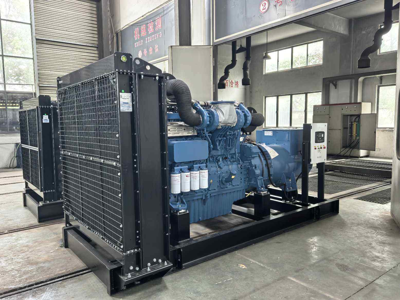
The upper limit comes from the alternator. A machine rated for 577A continuous accepts about 1.1 times that figure for an hour, which is 635A, and nothing above it without a temperature rise that shortens the winding life. The overcurrent setting therefore sits at or below 635A on a 400kVA frame.
The engine ceiling is often lower than the winding figure, and it is the one most orders miss. A set rated at 400kVA at 0.8 power factor delivers 320kW, and the engine may hold 350kW for an hour before the exhaust temperature runs past its limit. The lower of the two ceilings wins after conversion, and on most export sets the engine ceiling is the one that binds. Converting the engine ceiling to amperes at 0.8 power factor gives 632A, which sits just under the alternator figure on this frame.
Where is the lower limit of the setting?
The lower limit comes from the largest load that starts across the line. That motor draws six times its running current for two to four seconds, and the alternator adds its own recovery. On a 400kVA set with a 160kW motor, the start pulls 960A for 3s, so a curve that trips at 960A inside 3s takes the plant down every time the chiller restarts.
The margin between the two limits is then 635 ÷ 960 = 0.66, which means the setting has to sit at a current the start exceeds only for as long as the start lasts. Only an inverse curve gives that, because a fixed setting cannot be both. That ratio is the reason a set with a large motor needs a curve rather than a switch. Two limits and a curve between them is the whole method, and the curve is the part most orders leave out.
| Limit | Figure at 330kVA | Where it comes from | What it protects |
|---|---|---|---|
| Alternator thermal | 635A for 1h | 1.1 times rated current | The winding insulation |
| Engine overload | 350kW for 1h | 1.09 times rated kW | The pistons and the turbocharger |
| Largest motor start | 960A for 3s | Six times running current | Continuity of supply |
| Cable withstand | 760A continuous | Two derated 240mm² runs | The conductor and its insulation |
How does an inverse curve hold a motor start?
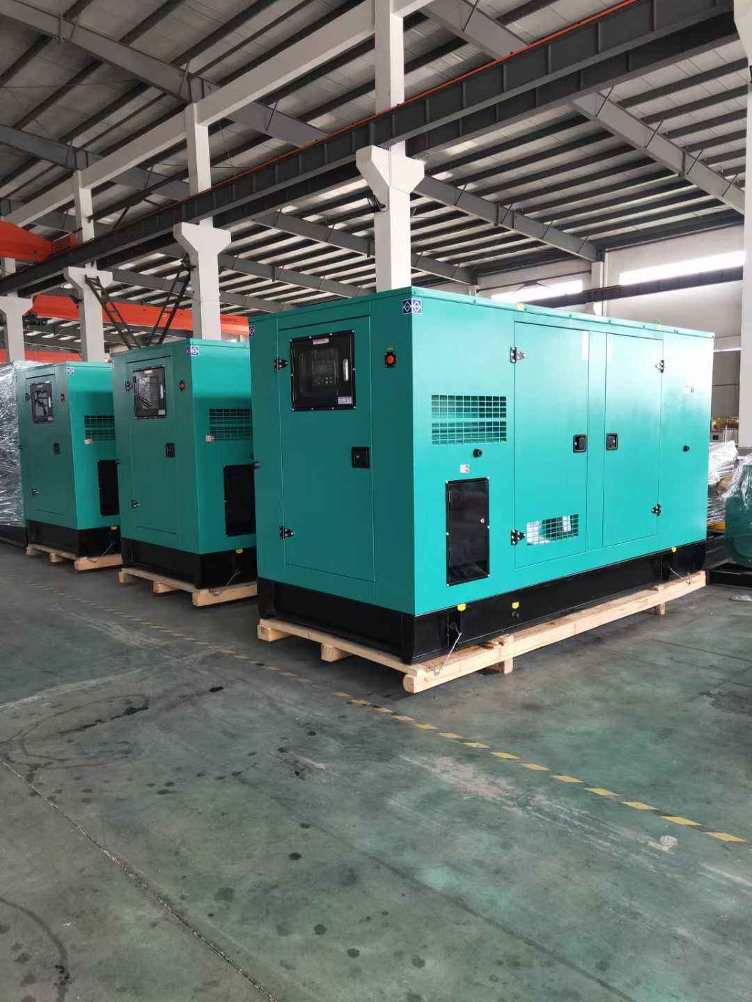
An inverse curve shortens its trip time as the current rises, so a 960A start clears in 8s while a 1,900A fault clears in 1.2s. The shape is set by the curve family, and the position is set by the dial. Most genset manufacturers fit a standard inverse curve and leave the dial at 1.0, which is the setting that causes most nuisance trips.
The 8s figure comes from the time dial. With the dial at 0.2 and a standard inverse curve, 1.5 times the setting gives about 8s. With the dial at 0.1 the same current gives 4s, which trips during the start. The difference between a working site and a tripping one is often that one number. The industry reference point for the long time element is 1.2 times rated current, and every published curve is drawn against it, so the dial moves the time while the 1.2 point stays where the sheet says.
What changes when the load is a drive rather than a motor?
A drive limits its own starting current to about 1.5 times the motor rating, so the lower limit moves down and the window widens. On a 400kVA set with four 160kW drives, the start pulls about 360A per drive rather than 960A, and the setting can then sit at 635A without nuisance tripping.
The drive adds a different problem, which is its charging current. A drive with a large direct current link draws a short pulse at power up, and that pulse can reach 4kA for 10ms. The instant element sees it and trips, so the setting has to include a short time delay that rides through the pulse without losing the fault clearance. A drive also feeds harmonic current back into the alternator, and that current heats the winding without appearing on the ammeter.
- Direct on line start, six times running current for three seconds.
- Star delta start, two and a half times for the first step and the same again for the second.
- Soft starter or drive, one and a half to two times for the ramp rather than a step.
How does the setting interact with the cable?
The setting has to sit below the derated cable rating, or the cable becomes the fuse. A 240mm² copper cable in a duct carries about 380A after derating, which is below the 577A the alternator delivers. That mismatch is common on an export site, and the answer is two cables rather than a lower setting.
Two runs of 240mm² carry 760A in the same duct, so the setting at 635A sits below the cable and the cable survives. The arithmetic is short and the consequence is not, because a cable that carries 577A through a 380A rating warms by about 25 ℃ over its design figure and ages at twice the rate. The cable check is the one that fails most often on export sites, and it fails before the set arrives rather than after.
Where does the setting go wrong at commissioning?
The commissioning dial is where it goes wrong, when an engineer raises it to stop a trip during the first transfer. The transfer applies a step load of the whole plant at once, which is a harder test than any single motor start, and the curve sees the sum. A dial turned up to pass that test leaves the site unprotected for the rest of its life.
The better answer is a step load rather than a setting. A transfer that brings the plant on in two stages, with the chillers delayed by ten seconds, keeps the current under 760A and the setting at 635A. Tesla Power writes that sequence into the commissioning sheet, because the site crew follows a sequence and ignores a note. A setting raised to pass a transfer is the single most common cause of an unprotected board, and it takes five minutes to avoid.
What does a parallel pair need from the setting?
Two sets in parallel each carry half the load, so each device sees half the current and the setting sits at half the single set figure. The pair then needs a second check, which is that one set alone can carry the full load after the other trips. The setting has to allow that overload for the time the second set takes to start.
On a pair of 400kVA sets, each device sits at 288A for its half share, and the remaining set takes 577A when the other trips. That is 2 times its setting, which a standard inverse curve clears in about 15s. A second set that starts in 8s therefore restores the pair before the curve operates, and the margin is the design. The pair also needs a check on the setting of the incoming device, because two curves that trip together leave the whole board dark. The reference condition is defined in the ISO 8528-1 rating definitions, which names the tolerance and the test point.
How is the setting proved before shipment?
It is proved by secondary injection into the trip unit, at three points: 1.1 times the setting, 1.5 times and 6 times. The first confirms the device does not trip in the long time band, the second confirms the curve, and the third confirms the instantaneous element. The three points take twenty minutes on a bench. The same frame appears in the 120kW set on the WP6 platform, where the plate states the same basis.
Yangzhou Tesla Power records the three times on the test sheet and leaves a copy in the panel. A site that later changes the dial has the original figures to compare against, which turns a debate about a nuisance trip into a reading against a reference. Chinese genset suppliers rarely supply that sheet, and the omission is felt two years later. The three points are enough to prove the curve without a full sweep, and a sweep proves little more for the time it takes. The same frame appears in the 1000kW container build for standby duty, where the plate states the same basis.
What should the offer state about the setting?
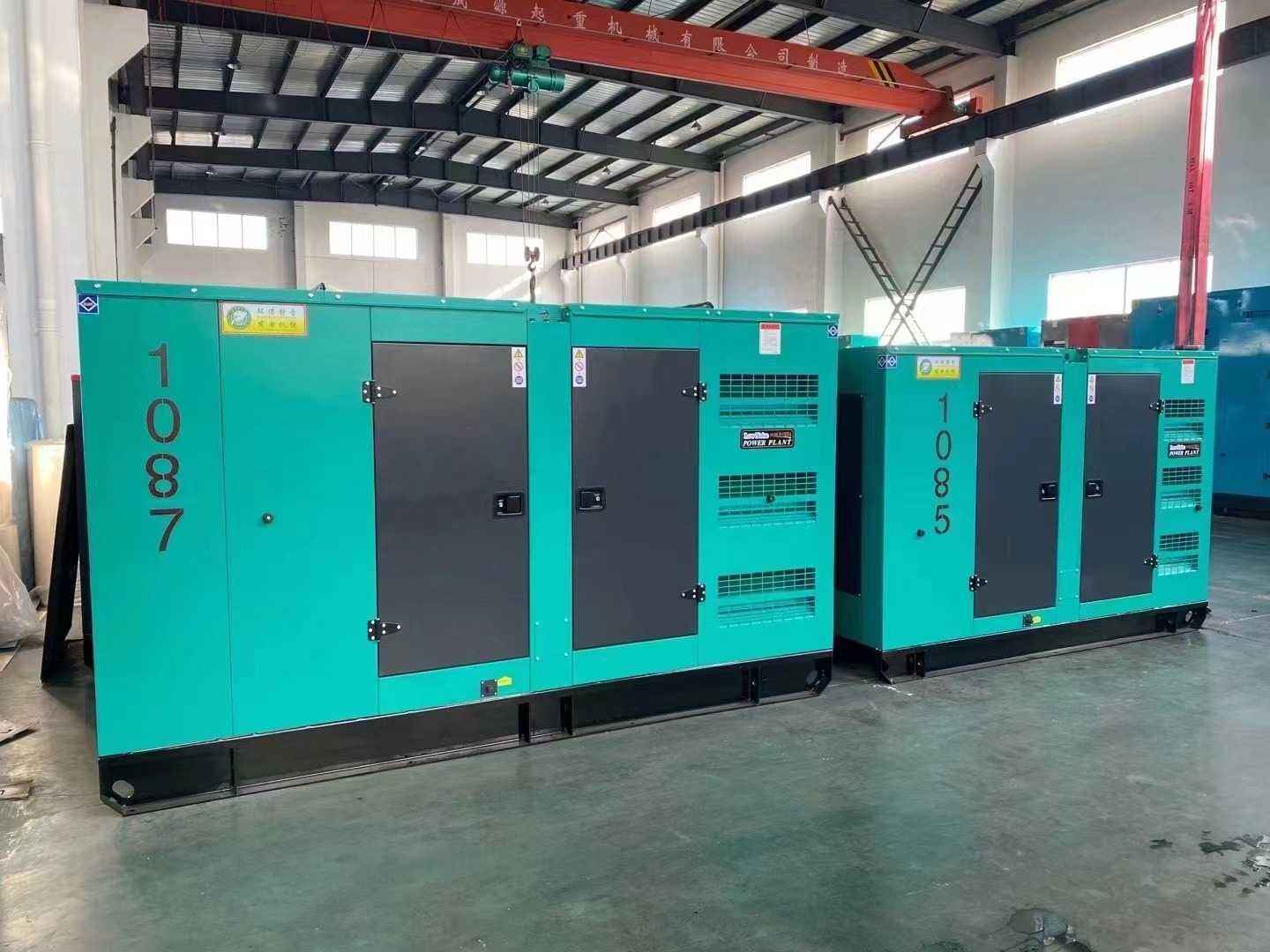
Five lines. The rated current, the setting as a multiple, the curve family, the time dial, and the instantaneous element in multiples. A quotation that states only the frame leaves the site to invent four of the five, and the invented set usually trips on the first hot afternoon. The same frame appears in the 400kW frame on the Weichai WP13 platform, where the plate states the same basis.
The ISO 8528-5 transient limits set the dip during a start, and the genset CE marking requirements put the relay setting inside the technical file. A buyer who asks for genset overcurrent setting for a site survey gets the five lines on the offer, and the fifth line is the one that stops the nuisance trips. A buyer who compares two offers on the five lines compares two protection schemes rather than two machines, and the fifth line decides how the site behaves on a cold morning. Tesla Power reads that figure on the site sheet before the plate is printed.
What does the site record after a trip?
A large motor with a long ramp deserves its own device, because a main curve cannot be tuned to one load without loosening everything else. The record after a trip carries the current at the moment of trip, the time, and the load that was running. Most controllers store all three, and the three together say whether the setting was wrong or the load was. A trip at 1.1 times the setting with a chiller start in the log is a setting problem, and a trip at 3 times with no start is a fault. The same frame appears in the 500kVA silent set with the ATS option, where the plate states the same basis.
Send the log and the setting to our export desk and the reply names the change rather than the symptom. Tesla Power Equipment keeps the original injection sheet beside the log, so the two together show whether the dial moved since the works test or the load grew past the design. The log is worth more than the arithmetic once a fault has happened.
Frequently asked questions about genset overcurrent setting
Either works, and the dial decides the difference. A genset overcurrent setting at 1.1 with a longer delay gives the same protection as 1.2 with a shorter one, and the first leaves more room for a motor start. Most sites do better at 1.1. A genset overcurrent setting for standby duty usually sits at the lower figure, because the load steps once and then holds.
Because a transfer applies the whole plant as one step, and the sum is larger than any single motor start. The fix is a staged restart rather than a higher setting, since raising the setting to pass that test removes protection for the rest of the year. Tesla Power reads that figure on the site sheet before the plate is printed.
The device protects the electrical path, and the engine has its own sensors for speed, temperature and oil pressure. The engine ceiling enters the calculation as a limit on the setting, not as something the device measures.
A standard inverse curve with a time dial near 0.2, which holds a three second start and clears a fault in about a second. A very inverse curve suits a set where the fault current is limited by a long feeder, because the curve is steeper at low multiples.
At least 10% below the derated cable rating, and more where the cable runs through a hot ceiling. A setting at the cable rating leaves nothing for a cable that is warmer than the calculation assumed. Tesla Power reads that figure on the site sheet before the plate is printed.
The device derates with panel temperature, so a panel at 55 ℃ moves the effective setting down by around 8%. The dial does not move, and the figure the device acts on does, which is why the panel temperature belongs on the sheet.
A genset overcurrent setting in a plant room with a large motor needs that element above the start, and it usually sits at 6 to 10 times the setting. It clears a bolted fault without waiting for the thermal element. It has to sit above the largest motor start, or the start trips it before the curve is reached.
Once a year, with the injection test at three points. A setting that has not moved in five years is still worth a test, because the trip unit drifts and the load grows, and the two move in opposite directions. Tesla Power reads that figure on the site sheet before the plate is printed.