
Genset reactive power is the magnetising current a load draws without doing work, and this calculation shows how it sets the alternator size before the kW figure does. Tesla Power Equipment reads that component from the load list, then states the kvar and the power factor so a supplier quotation matches the bus it feeds.
- Separate the kvar from the kW on the load list, because a motor and a heater of the same kW ask for very different current.
- Read the excitation ceiling off the data sheet, since a set held at unity power factor has almost no reactive reserve left.
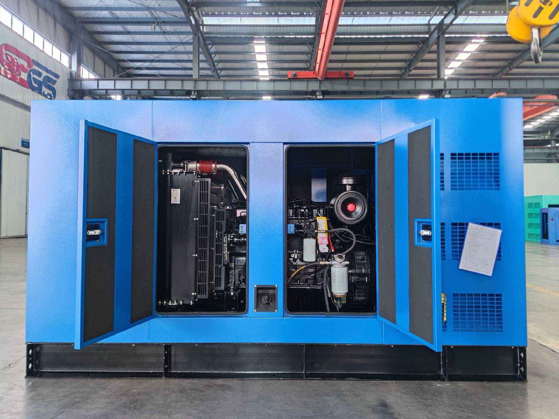
- Check the capacitor bank against the 500kVA silent set with the ATS option, where the kvar limit sits beside the rating.
- State the power factor the site runs at, because the same kW at 0.8 asks for a quarter more current than at unity.
What does genset reactive power decide on a load list?
It decides the alternator frame, and it does so independently of the engine. A 400kW load at unity power factor needs 400kVA of alternator, while the same 400kW at 0.8 needs 500kVA, and the engine behind both is the same. The extra 100kVA is copper and iron rather than diesel, which is why the two frames differ in price and not in fuel burn. Tesla Power reads that figure on the site sheet before the plate is printed.
The figure also decides the excitation margin. An alternator running at unity holds its field near the minimum, so it absorbs a step without touching the ceiling. The same machine at 0.8 already runs with the field raised, and a dip on a motor start can push it to the limit before the load is met. That margin is what a data sheet quotes and what a load list decides.
How much more current does a 0.8 power factor cost?
Current follows apparent power, so the arithmetic runs through kVA rather than kW. A 500kVA set at 400V delivers 722A per phase, and that figure holds whether the load behind it is resistive or inductive. The arithmetic behind it is short: a 400kW load at 0.8 gives 400 ÷ 0.8 = 500kVA, and 500kVA at 400V gives 722A. What changes with the factor is the work that current does, and the heat it leaves in the winding. Tesla Power reads that figure on the site sheet before the plate is printed.
The ratio is fixed by the power factor alone. At 0.9 the current is 11% above the unity figure, at 0.8 it is 25% above, and at 0.7 it is 43% above. A site that adds drives and motors over five years drifts down that table without changing its kW, which is why the factor on the original survey stops describing the bus.
| Frame | Current at unity | Current at 0.8 power factor | kvar at the rating |
|---|---|---|---|
| 400kVA | 577A | Same 577A, at 320kW | 240 kvar |
| 500kVA | 722A | Same 722A, at 400kW | 300 kvar |
| 550kVA | 794A | Same 794A, at 440kW | 330 kvar |
| 625kVA | 902A | Same 902A, at 500kW | 375 kvar |
| 800kVA | 1155A | Same 1155A, at 640kW | 480 kvar |
Read the table down the third column rather than across. The current does not rise when the factor falls on a fixed frame, because the frame is already sized for 0.8. What rises is the kilowatt the set delivers at that current, and the gap between the two columns is the capacity a buyer paid for and may not use. Most genset manufacturers quote the 0.8 column and leave the rest to a note.
Where does the reactive current come from in a plant?
Four sources cover most of it. Induction motors draw magnetising current across the air gap, and a motor at no load draws nearly full reactive current with almost no kW. Transformers draw it to establish the core flux, at about 5% of their rating even with no secondary load. Fluorescent and LED drivers draw it through the ballast or the input stage, and cable capacitance supplies a little back on a long run. Tesla Power reads that figure on the site sheet before the plate is printed.
The motor group usually dominates. A plant with 400kW of motors at part load can draw 250 kvar, while the same plant with 400kW of resistance heaters draws almost nothing. That is why a load list built from nameplate kW understates the alternator on a motor-heavy site, and why genset reactive power for a motor-heavy plant is read from the motor schedule rather than from the total.
What do over-excitation and under-excitation do to a set?
Over-excitation is field current raised above the level a given kW needs, which delivers more kvar to the bus and lifts voltage. It is how a set supports a weak bus and how two sets share reactive load. The cost is heat in the rotor, and the limit is the field winding rather than the stator, so the data sheet quotes a ceiling most sites read only after a hot afternoon.
Under-excitation is the opposite and is more dangerous on a generator. A field reduced below the level the bus needs makes the machine absorb kvar, which collapses voltage and can slip a pole on a set running in parallel with the mains. A 625kVA machine has a stability limit near 0.95 leading, and a site that switches in a bank at light load can cross it without touching the controller.
How do two sets share reactive load?
They share it through the voltage droop setting rather than through the governor. Two sets in parallel hold the same frequency by definition, so the reactive split follows the excitation curve each controller applies. A set with a 3% voltage droop takes less kvar than one at 1%, and the split stays proportional as the bus load changes through the shift.
The reactive split matters more than the kW split on a mixed site. A set with a lagging excitation curve carries the kvar for both machines and reaches its rotor limit while the second frame idles at unity. We have seen that on a two set installation where the droop was left at the factory setting on one controller and adjusted on the other, and the first machine ran 18 ℃ hotter on the rotor for a year.
When does a capacitor bank over-compensate a set?
It over-compensates when the bank supplies more kvar than the load draws, and the surplus has to go somewhere. On a mains supply the grid absorbs it. On a generator there is no grid, so the surplus current flows into the alternator and reinforces its own field, which lifts voltage. The effect is self-excitation, and it can run away inside a second.
The working limit is a bank no larger than about 25% of the set rating, so a 625kVA frame carries a bank up to roughly 150 kvar. Above that the risk depends on the load at the moment of switching. A site that sheds load with the capacitors still connected is the classic case, and the voltage rise that follows trips every drive on the bus before the breaker opens.
Which instrument reading separates kW from kvar?
A power analyser set to the power screen shows four numbers at once: kW, kvar, kVA and displacement factor. A clamp meter shows only current, and a current reading cannot say whether the amperes do work or magnetise iron. That is why a survey taken with a clamp meter and a calculator produces a kVA figure wrong in both directions.
Log for a week rather than an hour. The displacement factor falls at night when the motors run unloaded, and rises at full production when the same motors carry load. A site measured at midday in a busy week looks better than the same site measured on a Sunday, and the quotation follows whichever record the buyer sends.
How should a load list state the reactive figure?
Four columns do the work: the connected kW, the demand factor, the power factor at which the group runs, and the resulting kvar. Add a fifth for the largest motor, since a direct on line start draws reactive current at a low factor for two seconds and the alternator sees that as a step rather than as a steady figure.
- Lighting with electronic drivers runs near 0.95 and adds little kvar per kW.
- Induction motors at part load fall to 0.7 or below, well under the nameplate figure.
- Welding sets and arc furnaces sit near 0.5 and swing with the process rather than holding a value.
A list with kW alone leaves the supplier to assume 0.8, and that assumption is generous on a drive site and mean on a welding shop. Genset reactive power for the plant room then depends on a figure nobody measured, and two offers built on the same missing number still look comparable on price.
Which documents carry the reactive figure to the buyer?
Three do. The load list carries the kvar total the alternator is sized against. The alternator data sheet carries the kvar the machine delivers at rated voltage and the ceiling it reaches for a short step. The commissioning record carries the displacement factor measured on the day, and the three together show whether the site runs as surveyed. The same frame appears in the 120kW set on the WP6 platform, where the plate states the same basis. Tesla Power reads that figure on the site sheet before the plate is printed.
Ask for the kvar on the offer rather than a note that the set suits a 0.8 load. Conformity assessment for the alternator file reads the kvar line against the excitation ceiling on the data sheet. A quotation naming 300 kvar at 500kVA can be compared with a second one, and a quotation naming kVA alone cannot. The engineering notes on site planning cover the load list a buyer should send, and the ISO 8528-1 rating definitions fix the 0.8 reference both offers should name, and the NFPA 110 emergency power rules add the test schedule a hospital site follows.
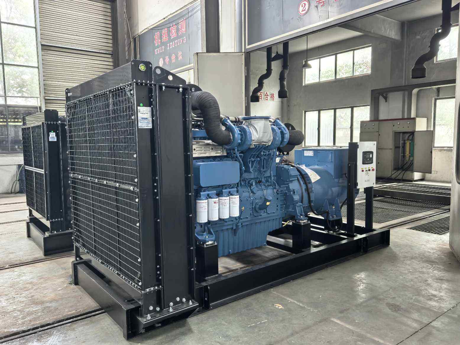
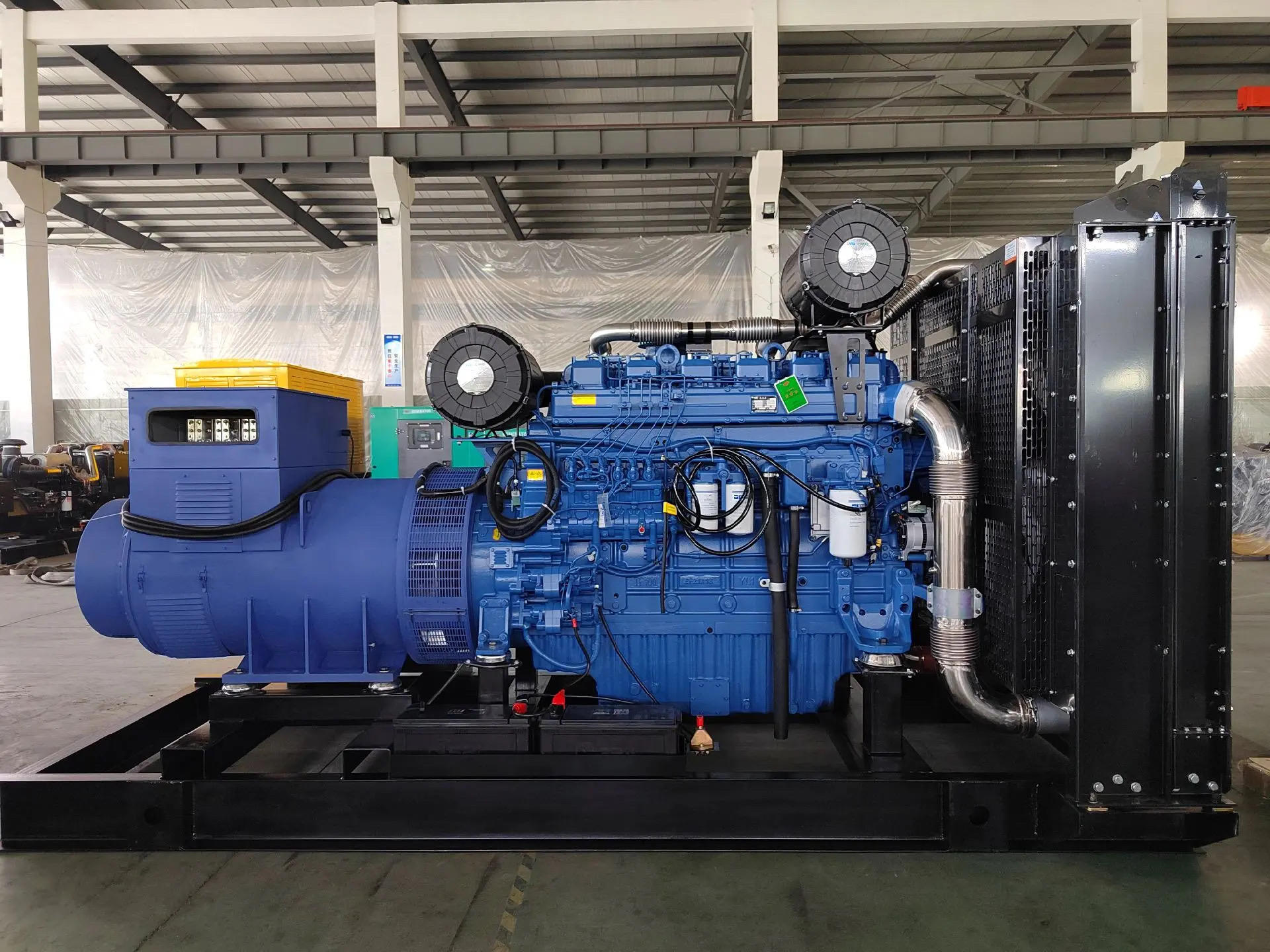
Yangzhou Tesla Power prints the kvar line beside the kW on every offer, and the factory and the test bay runs an inductive bank so the figure is measured rather than calculated, and the 400kW frame on the Weichai WP13 platform is tested on the same bank. A genset in parallel operation is checked on the same bank, since the reactive split between two controllers is easier to see than to argue about. The same two lines appear on the 1000kW container build for standby duty.
Frequently asked questions about genset reactive power
Because a typical motor load runs near that figure, and an alternator built for 0.8 carries more kvar per kVA than one built for unity. The rating is a convention rather than a limit, and a set with a larger alternator runs at a lower factor without harm.
The alternator delivers less current for the same kW and runs cooler, and the engine becomes the limiting component. A set sized for 0.8 and run at unity leaves kvar capacity unused, which is a cost rather than a fault.
It cannot raise the kW, because the engine sets that figure. It reduces the current the alternator supplies for the same kW, which frees winding capacity and lets a frame carry more motor load at the same temperature. Tesla Power sizes the bank against that effect.
Keep the bank under about a quarter of the set rating, so 150 kvar on a 625kVA frame. Above that the switching sequence has to guarantee the bank is off before load is shed, and a site without interlocks should stay well below the line.
It makes the machine absorb kvar, which drops voltage and can slip a pole on a paralleled set. The limit sits near 0.95 leading on most machines, and a large bank switched in at light load is the usual route to it.
Few state it unless the enquiry asks, and the ones who do print it beside the kVA. A supplier naming only the power factor leaves the alternator capacity open to interpretation, and the gap shows on the first hot shift of the season.
It halves the starting kvar and leaves the running figure unchanged. The magnetising current returns as soon as the motor reaches speed, so the alternator still carries it for the whole shift. Tesla Power reads that figure from the motor schedule.
Divide the running kW by the power factor to get kVA, then take the square root of kVA squared minus kW squared. A 240kW motor at 0.8 works out at 240 ÷ 0.8 = 300kVA, and the kvar is 180, which is the figure the alternator carries all shift.