
A genset emergency stop is the wired path that removes engine power in one motion, and it is the last control a crew touches when a set runs wrong. This guide collects the requirements a buyer should confirm, the standards that define the stop function, the tests that prove the circuit before handover, and the records that keep the proof. Tesla Power's engineering team runs the same checks at every works test, so the list below matches what we do. A stop untested under load is an unverified claim, not a feature. The checks below take one engineer and about an hour on a 400kVA set, and they catch the faults that a bench test hides: a jammed mushroom head, an undersized trip coil supply, and a stop path that bypasses the controller. The safety chain appears as a line item on every quotation we issue, so the buyer can see exactly what is wired before the set ships. Send your site layout with the enquiry, and we will mark the stop stations on the drawing for free.
- Confirm the stop category and the trip coil supply before you sign off a design.
- Walk the stop path on site and press every station under real load.
- Record the stop time and the restart lockout in the handover file.
- Ask the export help desk for the stop circuit drawing with your enquiry.
What does a genset emergency stop circuit actually do?
One motion must cut fuel or ignition and open the breaker, without waiting for the controller. The circuit wires every mushroom head in series into the safety chain. Press any head and the chain breaks. The controller then logs the trip and latches it, so the set stays stopped until someone resets it. That latch matters more than the trip. A set that restarts on its own after a stop has failed the whole point of the button.
The stop path must stay live even when the controller is off. Wire the coil supply from a fused feed that does not pass through the main controller. Tesla Power wires that feed as standard on every export frame. A stop wired only through the controller dies with the fault you are trying to escape. Every genset manufacturer we audit fails this check on one frame, so inspect the drawing, not the brochure. The trip coil supply deserves its own fuse and its own terminal number on the drawing.
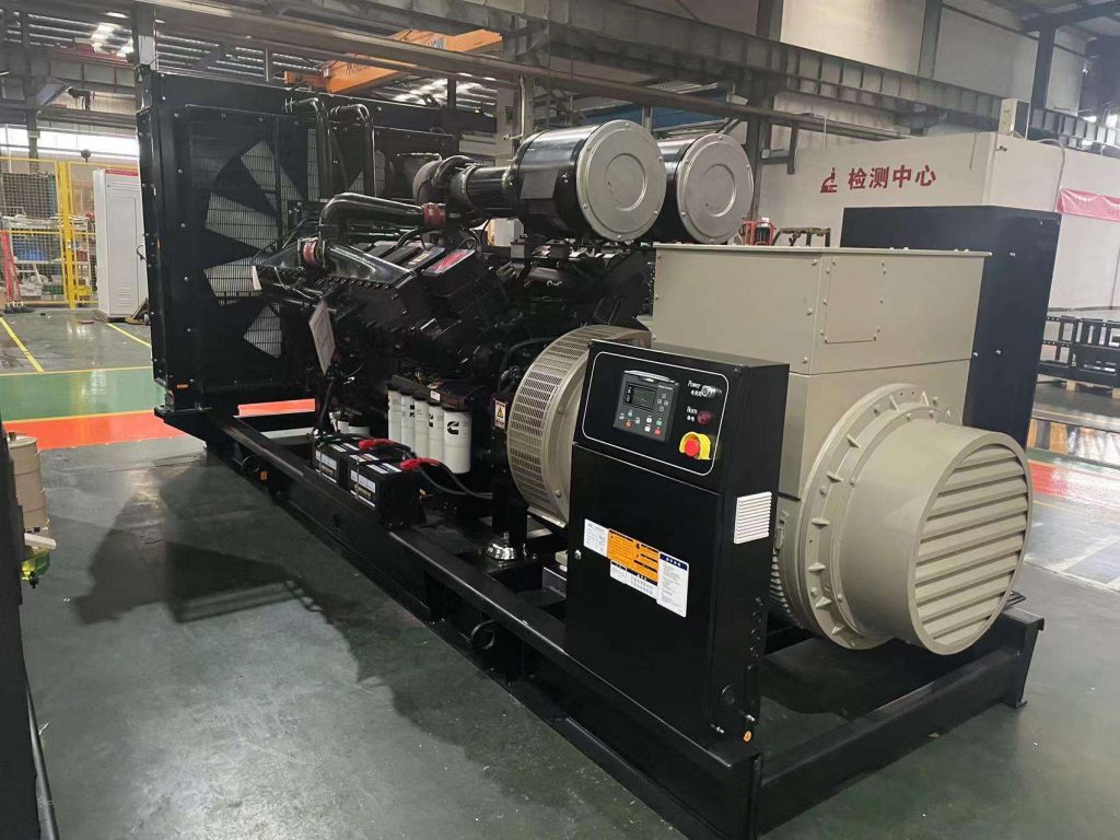
Category 0 or Category 1 stop: what decides?
Category 0 stops by removing power at once. The fuel solenoid de-energises and the breaker opens in the same stroke. Category 1 ramps the set down under control, then cuts power. Most diesel sets use Category 0, because an engine has no soft way to shed its fuel supply. A controlled ramp makes sense on large sets with big auxiliary loads, where an instant cut would slam a downstream process. Pick one category, wire for it, and label the cabinet with it.
The size of the set decides how hard the choice bites. Work the numbers for a 400kVA frame at 400 V. The line current at rated output is 400kVA / (1.73 x 400 V) = 577 A per phase. A breaker that carries 577 A must open cleanly on the stop stroke, so the coil supply has to hold through the whole travel. At 50 Hz the opening takes a few cycles. If the coil supply sags mid stroke, the breaker hangs and the arcing contacts carry the fault. A 1250kVA set in a container carries about 1804 A on the same 400 V basis, and the arithmetic scales the same way.
Which standards govern the stop circuit?
Three documents cover most export projects. ISO 13850 defines the stop function itself: the mushroom head, the direct opening action, and the reset behaviour. IEC 60204-1 defines the stop categories and the wiring rules for the safety chain. NFPA 110 covers the performance a standby set must show on site, including how fast the protective functions must act. Tesla Power cites all three by number in the offer, so a buyer gets a comparable bid from every supplier on the list.
| Requirement | Source | What the buyer checks |
|---|---|---|
| Stop function and reset | ISO 13850 | Mushroom head latches, reset needs a manual action |
| Stop category and wiring | IEC 60204-1 | Category label on the drawing, coil supply fused |
| Protective function performance | NFPA 110 | Trip acts within the stated time at the site test |
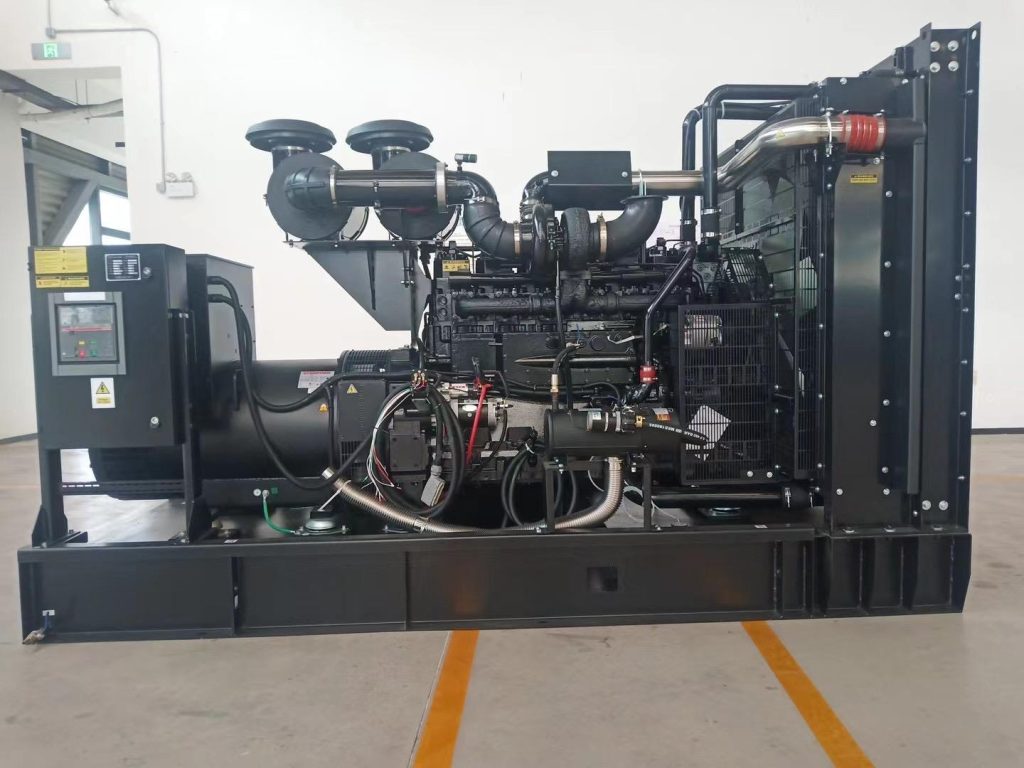
Read the standards against the drawing, one clause at a time. The ISO 13850 standard costs less than one hour of site rework, and the IEC catalogue lists the wiring rules in the same format. Cite the edition year in the purchase order, because the clauses move between editions.
Where should a stop station be mounted?
Place one station at the set and one at the point of use. The set station belongs on the canopy wall, within reach of the fill point and the radiator end. The point-of-use station belongs where an operator stands, rarely beside the set. A genset for hospital wards puts the second station at the switch room door. A genset for rental fleets repeats it on the distribution board. A genset for mining camps runs the stop pair to the camp office, because that is where the duty electrician sits at night.
Mount height stays the same everywhere: between 0.6 m and 1.7 m, on a clear wall, with the head unobstructed. Keep at least 1 m of clear floor in front of each station. A station behind a stacked pallet fails an audit without a single electrical fault. Paint nothing over the head, and fit a protective collar so a forklift cannot shear it. Tesla Power labels each station with the set serial number it stops.
How do you test a genset emergency stop on site?
- Run the set at 50% load and let the readings settle.
- Press the set-mounted head and record the stop time from press to zero.
- Reset the latch and restart, then repeat at the remote station.
- Confirm the controller logs the trip with the station number.
- Check that the set stays down until a manual reset clears it.
A 400kVA set should stop inside a few seconds from the press. The exact figure comes from the breaker and solenoid data sheets, not from habit. Log the stop time, the load level and the station pressed in one row. Two stations on one set need two rows. A single combined row hides a dead remote station.
What does the stop test record need?
The record carries four facts per press: the station, the load, the stop time and the reset action. Add the meter readings before and after, so a reviewer can see the set carried real load at the moment of the trip. Sign the sheet on the day of the test. A shutdown trip record from an earlier service visit pairs well with it, because the two sheets prove the chain and the engine protection act independently.
Keep the drawing that was as-built on the test day. Circuits drift during service, and the drawing that matched last year may not match today. A China genset supplier that ships the as-built drawing with the set saves the buyer this argument. Tesla Power archives each sheet against the set serial number, and scans it before the container leaves the works. The as-built drawing is the sheet an insurer will ask for first.
Which mistakes trip crews up most often?
The common fault is a stop wired through the controller. The set passes a bench test with the controller healthy, then fails on site the day the controller itself is the problem. The second fault is a shared coil supply, where the stop and a status lamp draw from one fuse. The lamp blows, the fuse goes, and the stop dies with it. The third is a remote station installed after commissioning and left untested under load.
Each fault costs an hour to find during a factory visit. Each costs a day on site, plus a callout. A genset manufacturer that runs a full-load stop test before shipment removes all three. Tesla Power Equipment presses every station at 50% load in the works, and the test row lands in the handover file.
Read our published test notes to see the format before you set your own acceptance rule.
A fourth fault lives in the spares kit. The mushroom head and the trip coil are wear items, and a site that stocks neither waits on a flight for a part worth a few dollars. Ask for one spare head and one spare coil per set in the offer. Fit them to the store list, and record the part numbers beside the breaker data sheets. A crew with the spare on the shelf fixes the chain in an hour. A crew without it waits a week.
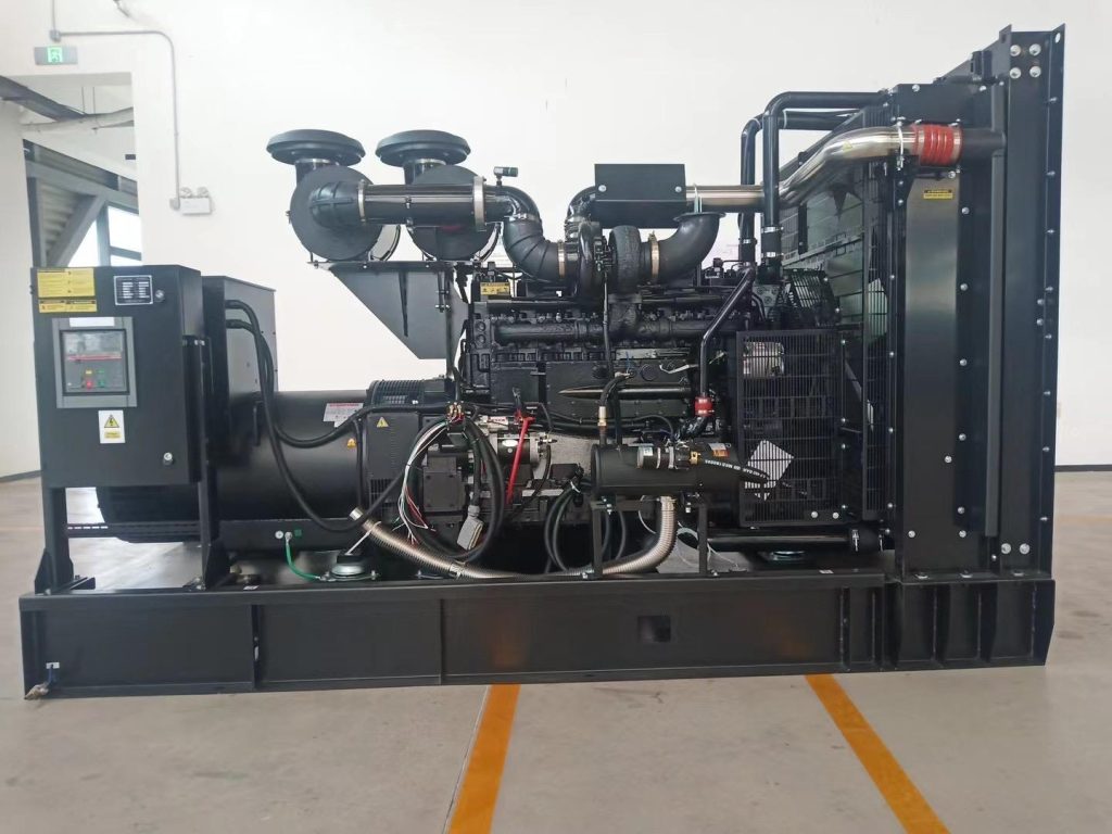
What should you confirm before you order?
Put four lines in the enquiry. State the stop category and station count. Ask for the coil supply to be fused independently, and for the as-built drawing to ship with the set. Ask for the factory stop test at 50% load with the record in the handover file. Tesla Power returns a marked drawing against each of the four lines, so the offer is comparable across bids, and the IEC publications index gives you clause numbers to cite.
Check the compliance file too. The CE marking requirements for a genset cover the safety chain, and the conformity assessment for the EU market names the standards the set was checked against. See the 500kVA sound-attenuated set for a worked example of the rating and the option list, then email our export desk with your station count for a drawing-based quotation. A 1250kVA containerised KTA50 genset follows the same four lines, scaled to its breaker size. A manual reset at the station is part of the same design review.
Frequently asked questions about the genset emergency stop
No. The normal stop is a controlled sequence through the controller. The emergency stop is a safety action that cuts power in one stroke. Use the normal control for daily operation, and keep the stop for faults. Frequent use of the stop head wears the latch and hides real emergencies.
Two as a baseline: one at the set and one at the point of use. Large sites add one per occupied work zone within reach of the set. Each station is wired in series, so each adds a fault point. More stations mean more test rows, not more safety per button.
No. The stop path must break the fuel or breaker supply directly, independent of the controller. A controller that has locked up must not lock up the stop with it. Inspect the drawing for a fused, dedicated coil supply before you accept the design.
The value comes from the breaker and solenoid data sheets, typically a few seconds at 50 Hz. Record the measured time and compare it with the data sheet figure. A time that doubles between tests points to a sagging coil supply or a sticky breaker mechanism.
Test every station under load at each service interval, and at least once a year for standby sets. Test after any controller change, any breaker service, and any site rewiring. A station pressed during a real emergency needs a fresh test row before the set returns to standby duty.
A person does, at the station that tripped. The head twists to release, then the controller reset clears the latch. No set should restart from a remote desk without the local reset. Keep the reset authority with the crew on site, and log who reset it in the record.
Ask for it in writing. Yangzhou Tesla Power presses every station at 50% load during the works test and puts the row in the handover file. If a supplier cannot show that row, plan a stop test as part of your site acceptance before the set carries load.