
Hospital standby generator requirements are set by NFPA 110 Level 1 and Type 10 starting, anchored to a documented essential load list. The right hospital standby generator is sized to the load, runs on stored fuel for prescribed hours, and proves its transfer sequence before commissioning. Send the load schedule and runtime target with the RFQ to the Tesla Power engineering desk.
- Level 1 EPSS covers life-safety branches: operating rooms, ICU, emergency lighting, fire pumps.
- Type 10 sets must reach rated voltage and frequency within 10 seconds and pick up the entire essential load.
- The essential load list, not the building total, sets the generator rating and the step-loading profile.
What counts as a hospital standby generator under NFPA 110?
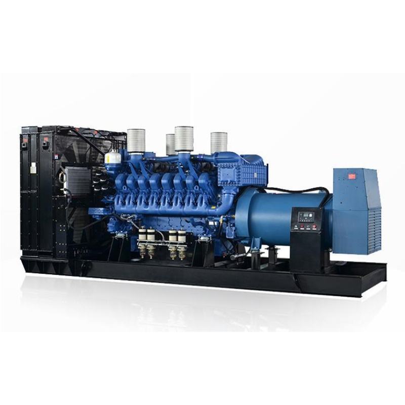
NFPA 110 separates the emergency power supply system into three parts: the energy source, the power conversion equipment, and the distribution side with the transfer switches. A hospital standby generator is the energy source and a piece of the conversion equipment; the transfer switches and the EPSS sit downstream. The standard calls the whole package the Emergency Power Supply System, or EPSS, and it grades the set, the transfer switches, and the room as one system. If any one part underperforms, the EPSS as a whole fails the acceptance test. Hospital standby generator requirements are written for the system, not for the genset alone, and a hospital standby generator manufacturer exporting to a Level 1 site will be asked for paperwork on every link in that chain. Tesla Power projects keep that paperwork in the same bound file as the FAT record, so the buyer's engineer does not chase two binders.
Level 1 vs Level 2 EPSS: which class does a hospital need?
Level 1 and Level 2 are the two EPSS classes that decide what a hospital standby generator must prove. The class is set by what the load protects: human life, or something less critical. That single decision drives every test interval, every maintenance step, and every line of the handover file.
- Level 1 — life-safety loads; failure risks loss of life or serious injury.
- Level 2 — less critical loads; failure causes discomfort or interruption.
- Hospitals sit at Level 1 for operating rooms, ICUs, and fire pumps.
Level 1 EPSS serves life-safety loads, where a failure leads to loss of life or serious injury. Hospitals fall under Level 1 for operating rooms, ICUs, recovery wards, emergency lighting, and fire pumps. NFPA 99 and most local codes place these spaces at Level 1 by their wording. A small clinic may sit at Level 2 in some jurisdictions, but a general hospital does not. The level sets the testing cadence, the maintenance interval, and the runtime expectations.
A hospital standby generator for life safety sites is therefore a Level 1 set with the matching documentation, the weekly exercise, and the annual 100% load-bank run on the schedule. The level is a contractual line on the FAT paperwork, not a footnote. Tesla Power keeps the same paperwork line by line, so the buyer's engineer reads the FAT record against the spec without translation. That single line drives every later test and every handover file for the project.
Sizing a hospital standby generator from the essential load
The rating comes from the essential load list, not from the connected building load. Start with the running kW of each essential load, add the motor starting kVA at the correct power factor, and apply the step-loading sequence that the transfer switch will use. For a typical 200-bed export hospital: essential load sits in the 500–800kW running range, motor starting adds roughly 200kVA, and the standby set is rated 1000kVA (800kW at 0.8 pf) sized to carry that load in a controlled two-step sequence. The arithmetic: 800kW ÷ 0.8 pf = 1000kVA. The next approved size up is 1250kVA (1000kW at 0.8 pf), which gives headroom for future expansion; the size below is 800kVA (640kW at 0.8 pf), which is tight once motor inrush is included. A second set is added for N+1 redundancy: install 2 × 1000kVA (800kW) so either set can carry the full essential load alone while the other is offline for service. The help and advice library carries a worked sizing sheet for a 200-bed hospital, with the load list and the step-loading profile filled in.
Hospital standby generator sizing is dominated by motor starting, not running load. A common mistake is to take the running kW, add 20%, and order the set. That misses the inrush of the fire pump, the MRI chiller, and the operating-room UPS, and the alternator voltage collapses when the ATS closes. The one item that fixes this is a step-loading sequence that staggers the largest motors across 5–10 seconds. The transfer switch is the device that enforces that sequence; the alternator is the device that has to ride it out. The 1250kVA hospital standby set in the catalogue is rated for that inrush profile and ships with the matching alternator data. Tesla Power sizing reports cite the approved power segment and the engine model on the same page, so the buyer's engineer can read the two numbers together.
The step-loading profile is set by the transfer switch, not by the genset. The ATS closes on the essential bus in one step, two steps, or three steps, and each step is a separate inrush event for the alternator. A 1000kVA set can ride a two-step close with the fire pump on step 1 and the rest on step 2; a three-step close needs a larger alternator or a softer motor starting scheme.
The arithmetic reads: 800kW running + 200kVA motor inrush on step 1 = 1000kVA at 0.8 pf. Step 2 adds the remaining 200kW, which is well inside the alternator's overload envelope for 10 seconds. The 10-second window is the design point for the engine throttle, the alternator excitation, and the switchgear close time, all of which sit inside the Type 10 envelope.
NFPA 110 Type and Class for a hospital standby generator
| Parameter | Allowed values | Hospital choice |
|---|---|---|
| Type (seconds to carry load) | 10, 15, 60 | Type 10 |
| Level | 1, 2 | Level 1 |
| Class (hours of stored fuel) | I, II, III, IV, V, X | Class II or higher |
| Power factor | 0.8 (standard) | 0.8 |
| Weekly exercise | ≥ 30% nameplate kW, 30 min | 30%, 30 min |
| Annual load-bank run | 100% nameplate kW, class duration | 100% |
Runtime, fuel, and Class X hours: how long must it run?
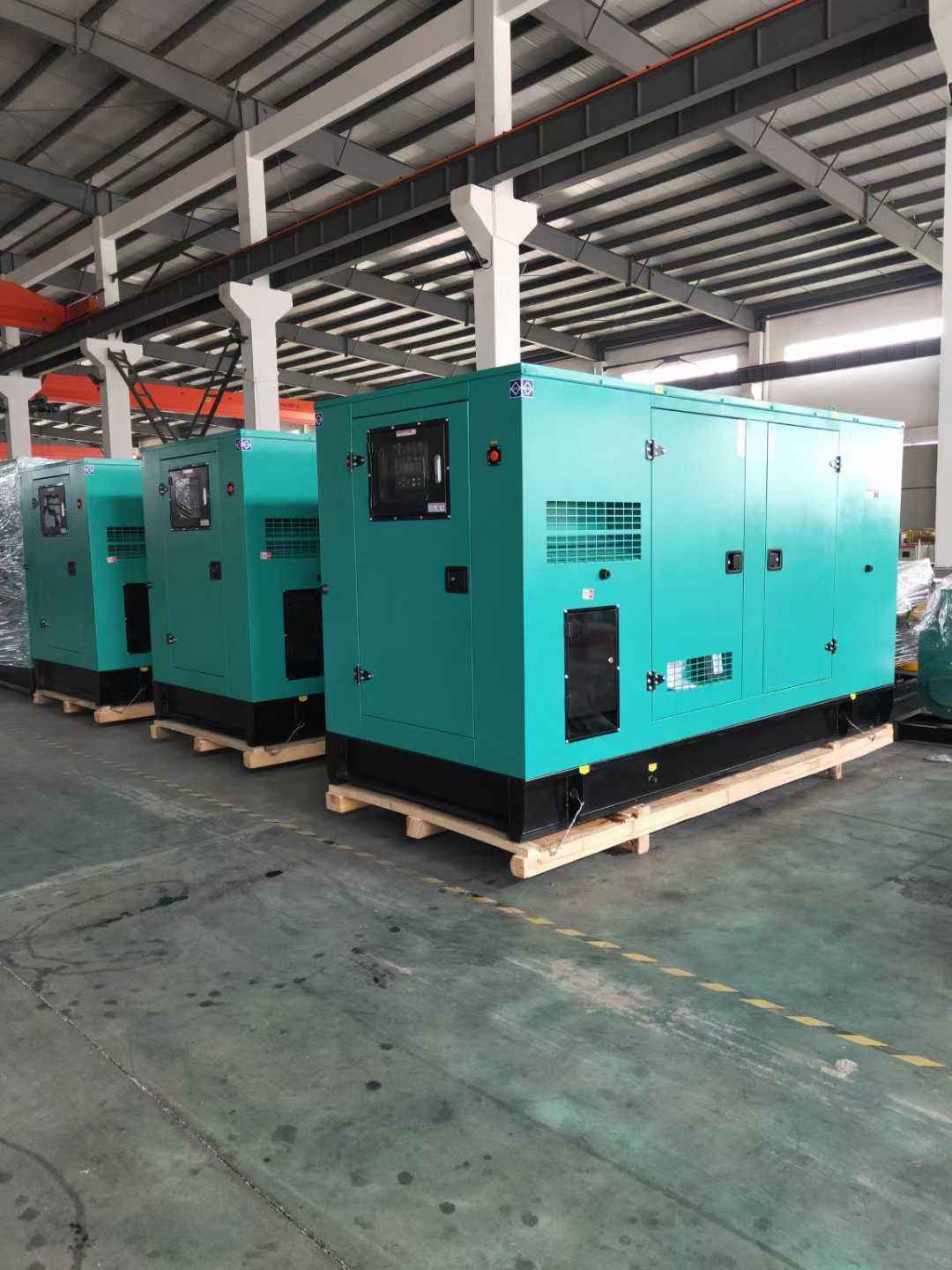
NFPA 110 defines Class by the minimum hours the EPSS must run on stored fuel at rated load. Class II sets a 6-hour baseline; Class III, IV, and V extend runtime for sites that must wait out a long grid outage. A hospital in a region with unreliable mains sits in a higher class, and the day tank plus bulk tank are sized to match.
- Class I — 2 h of stored fuel.
- Class II — 6 h; the common hospital choice.
- Class III to V — 8 h up to 100+ h for long outages.
A 1000kVA (800kW) diesel standby set at 75% load burns roughly 200 L/h, depending on the engine model and ambient conditions. At 50% load the rate drops to about 130 L/h; at 100% load it rises to about 270 L/h. Class II at 75% load therefore needs roughly 1200 L of usable fuel, plus a 25% reserve for measurement error and tank geometry.
Fuel consumption does not scale linearly with load. At 25% load a 1000kVA set burns roughly 80 L/h, about 0.4 L per kWh delivered; at 75% load the rate is 200 L/h, about 0.33 L/kWh. The most efficient point sits between 70% and 85% of nameplate kW, where brake-specific fuel consumption is at its minimum. Below 30% load the engine runs cool and combustion stays incomplete. Tesla Power fuel reports name the engine model and test cycle on the same line as the L/h figure, so the number is traceable to a data sheet.
How does the transfer sequence shape the Type 10 requirement?
Type 10 means the EPSS must reach rated voltage and frequency, and pick up the entire essential load, within 10 seconds of the normal source failing. Type 15 allows 15 seconds; Type 60 allows 60 seconds. Hospitals are Type 10, not Type 15. The transfer switch senses the loss of mains and signals the engine to start.
- Type 10 — 10 s to full load; hospitals and life-safety branches.
- Type 15 — 15 s; some Level 2 sites.
- Type 60 — 60 s; non-critical loads only.
The transfer switch waits for voltage and frequency to stabilise, then closes on the essential bus. The 10-second clock starts at the loss of mains and stops when the essential load is fully carried. Engine starting time, alternator build-up, and switchgear close time all sit inside that 10-second window. The 500kVA containerised standby set in the catalogue is built to the same Type 10 envelope and shares the FAT template.
A hospital standby generator supplier quoting a Type 10 set should show a time-stamped test record from the FAT, with engine start, alternator build-up, and step-loading curves on the same page. The record, not the brochure, is the proof. The NFPA 110 standard is published by the National Fire Protection Association; the buyer should ask for the edition year that the local authority has adopted, since that edition is the one the inspection will cite. The requirements text is the NFPA 110 emergency power standard.
Ventilation, exhaust, and the generator room layout
A 1000kVA standby set rejects a substantial heat load to the room at full load, alongside the radiator discharge that has to go somewhere. The room needs supply air sized to the combustion requirement, exhaust air sized to the heat rejection, and a discharge path for the radiator that does not recirculate back into the intake. A common mistake is to size the louvre for combustion only and ignore the heat load; the room temperature then drifts up, the set derates, and the essential load no longer rides. Hospital standby generator for life safety sites also need a separated fuel line, a day tank inside the room, and a fire-rated cable entry. The one-line diagram below shows the typical topology. The prime versus standby power rating classes page explains how the room cooling load changes between the two ratings.
Acceptance testing: what Level 1 EPSS must demonstrate
A Level 1 EPSS is tested at the factory (FAT) and again on site (SAT). The FAT record should show cold-start time, step-loading behaviour at 25%, 50%, 75%, and 100% of rated load, voltage and frequency recovery, and a 4-hour run at rated load. The SAT repeats the cold-start and step-loading, plus the 10-second Type 10 transfer test against the real building load. Fuel consumption at 75% load and at 100% load is recorded; the numbers go into the handover file. Yangzhou Tesla Power documentation for export includes both records, with serial numbers, dates, and witness signatures on every page. The ISO 8528-1 power ratings explained page names the ESP rating that the FAT record should cite.
Maintenance and load-bank running for hospital standby sets
A standby set that sits idle for long periods will wet-stack, leak coolant, and fail to start. NFPA 110 prescribes a weekly exercise at no less than 30% of nameplate kW for 30 minutes, plus an annual load-bank run at 100% of nameplate kW for the duration required by the class. The weekly exercise keeps the engine warm and the alternator dry; the annual run proves the set can carry full load. Skipping the annual run is the single most common cause of an EPSS failing its real outage, and the failure shows up on the day the grid is down for six hours. Tesla Power Equipment schedules the weekly and the annual exercise on the same maintenance contract, and the records go into the same handover file. The generator room ventilation sizing page links the maintenance plan to the airflow requirement so the room does not drift out of spec between visits.
The weekly exercise is logged in the EPSS maintenance file with the start time, the run time, the load, and any alarms. The annual load-bank run is logged with the same fields plus the voltage, the frequency, the exhaust temperature, and the fuel consumed. Both records are auditable; both go into the same handover file, and both are reviewed at the annual EPSS audit.
A hospital standby generator for life safety sites also needs a fuel sample at every oil change, a coolant analysis every 12 months, and a battery impedance test every 6 months. The fuel sample catches water and microbial growth before they block the filters. The battery test catches a weak cell before it strands the set on a cold morning when the grid is down and the ATS is calling for start.
Cross-border compliance: CE marking and (EU) 2016/1628
A hospital standby generator for export to a European project faces the Machinery Regulation, the (EU) 2016/1628 NRMM emissions regulation, and the Low Voltage Directive, plus the EN 60204 electrical safety family. Documentation is the deliverable: the technical file, the declaration of conformity, the noise test record per the EU Outdoor Noise Directive, and the emissions test record per (EU) 2016/1628. Hospital standby generator CE marking requirements are not a sticker; they are a file the buyer keeps for ten years. For a U.S. or Middle East project the same logic applies, but the test house and the standard numbers change. A China hospital standby generator supplier shipping to these markets will keep a conformity dossier per serial number and provide it on request.
FAQ: hospital standby generator requirements from Tesla Power
Type 10, Type 15, and Type 60 set the maximum seconds the EPSS is allowed to take from the loss of normal power to carrying the full essential load. The numbers are 10, 15, and 60. Hospitals sit at Type 10 because the essential loads are life-safety branches. A 10-second cold-start with a step-loaded hospital bus is the design point for the engine sizing, the alternator excitation, and the transfer-switch close time. Slower types are used where a brief interruption is tolerable.
At 75% of rated load, a 1000kVA (800kW) diesel standby set burns roughly 200 L/h, depending on the engine model and the ambient conditions. At 50% load the rate drops to about 130 L/h; at 100% load it rises to about 270 L/h. These numbers feed the day tank and the bulk tank sizing. A Class II runtime of 6 hours at 75% load needs roughly 1200 L of usable fuel, plus a 25% reserve. The fuel rate per kWh falls as the load rises.
A 200-bed hospital typically presents 500–800kW of essential load once non-essential HVAC and laundry are shed. A single 1000kVA (800kW) set covers the load if the step-loading sequence is well managed. For Level 1 EPSS, most authorities prefer N+1: install 2 × 1000kVA so that one set can carry the full essential load while the other is offline for maintenance. The cost of the second set is small compared with the cost of an outage during a planned service. Hospital standby generator for ICU and operating-room loads falls in this N+1 design point.
NFPA 110 prescribes an annual test at 100% of nameplate kW for the class duration, plus a weekly exercise at no less than 30% of nameplate kW for 30 minutes. The annual test proves the set can carry full load; skipping it leaves wet-stacking and derating risk in place. A manufacturer that skips the load-bank test on its own floor is one to question.
The FAT record with cold-start time, step-loading behaviour, voltage and frequency recovery, and a 4-hour run at rated load. The SAT record repeats the cold-start and step-loading on site, plus the 10-second transfer test against the building load. The nameplate, alternator, and engine data sheets, the control panel schematic, and the conformity dossier for the destination market complete the file. For Europe that includes the (EU) 2016/1628 NRMM emissions record; for a U.S. project it includes UL 2200 where the spec asks for it.
A diesel standby set that is correctly sized, exercised weekly at ≥30% load, and given its annual 100% load-bank run will run for 20,000 to 30,000 hours before a major overhaul. Without the load-bank run, the alternator windings and the engine exhaust side degrade far sooner. Hospital standby generator warranty terms are written against this run profile; a set that is exercised to spec keeps the warranty intact, while a set that is not is excluded.
A standby generator is the engine and the alternator. An EPSS is the system: the engine, the alternator, the transfer switches, the paralleling switchgear if any, the fuel system, the room, and the controls. Hospital standby generator requirements are written for the EPSS, not for the genset alone. Buying a good genset and a poor transfer switch, or a good transfer switch and a poorly ventilated room, still produces a failing EPSS.
Send the essential load list, the runtime class, the transfer-switch spec, and the destination country with the RFQ; Tesla Power will return a sized proposal with FAT and SAT test plans attached.