
A generator excitation failure rarely announces itself with noise from the engine, because the engine keeps turning while the alternator stops making voltage. We see the pattern on export sets every week: the controller shows normal speed, normal oil pressure and normal fuel, yet the output sits at zero or drifts between 180V and 230V with no load change. That split between a healthy prime mover and a silent electrical side is the clue, and it is where the diagnosis should begin. Tesla Power treats the fault as a ladder, and this guide shows how to work down it: sensing circuit first, automatic voltage regulator second, exciter and rotating diodes third, residual magnetism last. Work down the rungs in order and the cause shows itself within an hour on most frames. The steps below give the readings that clear each stage, and the evidence a supplier needs before you request a quotation for parts.
- Read terminal voltage with the breaker open before anything else is touched.
- Separate engine data from electrical data, because only one side of the set is sick.
- Test the AVR sensing input before replacing the regulator itself.
- Keep the readings beside the range of export frames the factory builds, so the supplier quotes against evidence rather than guesses.
What is a generator excitation failure and how do you spot it?
The excitation system is the small electrical world behind the main stator. A supplementary winding feeds direct current into the field, and that current decides the voltage the set holds under load. When the excitation chain breaks, the machine keeps its speed and loses its voltage, which is why an excitation fault so often gets misread as a controller problem.
Spot it with three readings taken inside one minute. Terminal voltage with the breaker open. Field current where the data sheet gives a figure. Residual voltage across the exciter stator with the set at rest. Low or absent values on the electrical side, with clean engine data beside them, place the fault in the excitation path and nowhere else.
Which symptoms point to the field circuit before the engine?
Four symptoms carry most of the weight. Voltage that fails to build from a standing start. Output that collapses the moment a load steps on. A figure that hunts up and down while the engine holds steady speed. Voltage that recovers after the set is stopped and restarted. Each one maps to a specific test, and generator excitation in dusty sites adds a fifth pattern, where conductive dust across the exciter stator leaks the field current to earth.
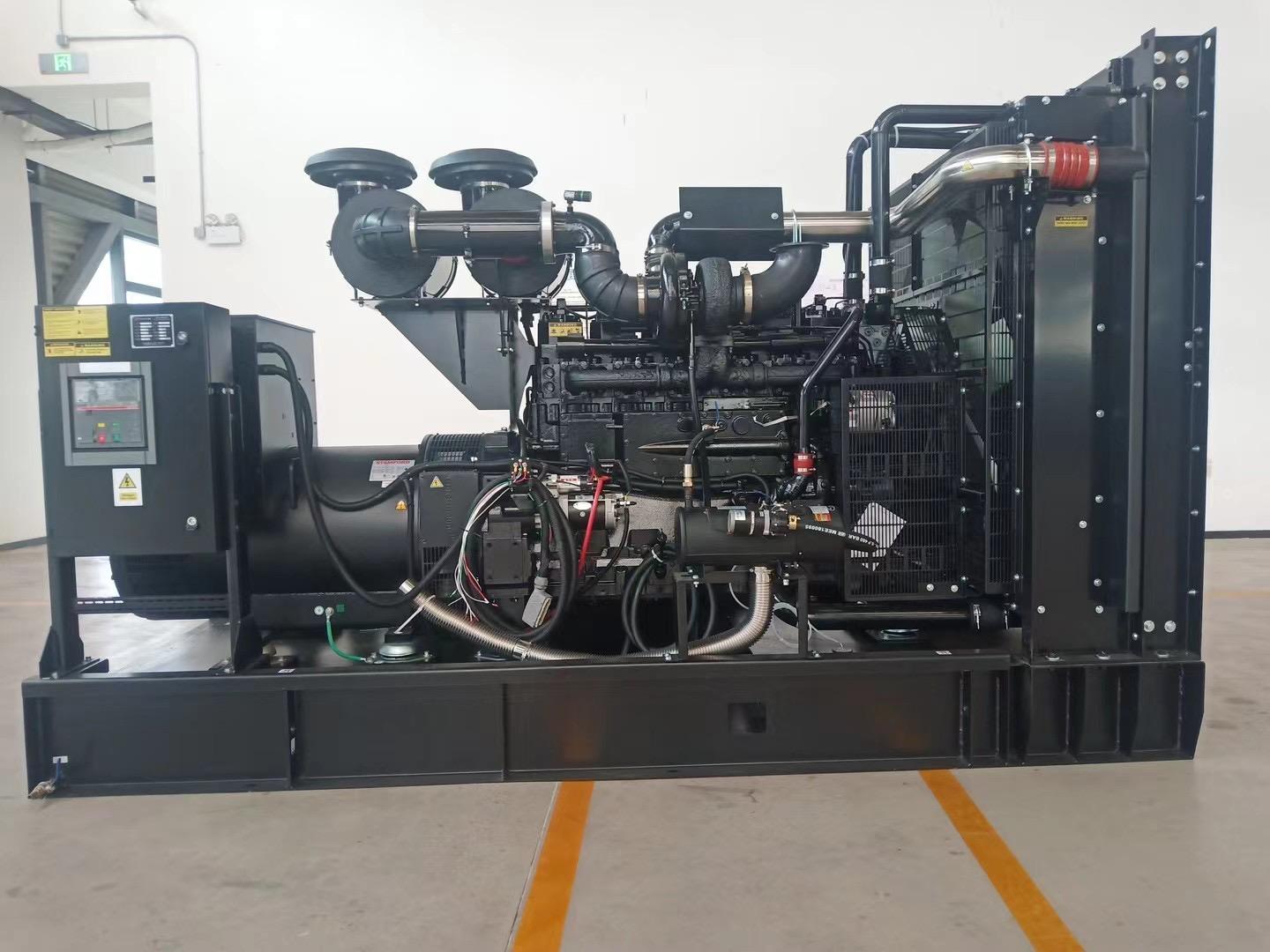
Tesla Power Equipment asks service crews to log the symptom and the reading together, because the pair decides which part ships. A collapsed output under load with a healthy open-circuit figure points at the rotating diodes, not at the regulator, and the same reading appears on the 400kW frame with the Weichai WP13 engine more often than on any other build we ship. A standing zero with normal residual points at the sensing input. The table below turns the four symptoms into a verdict you can send by email.
| Symptom | First test | Verdict the reading points to |
|---|---|---|
| No voltage from a standing start | Measure residual voltage at the exciter stator | Residual magnetism lost, or field circuit open |
| Output collapses under load | Test each rotating diode both ways | One or more diodes shorted or open |
| Voltage hunts at steady speed | Check the sensing leads and the AVR reference | Sensing circuit fault, not the field |
| Low output with hot windings | Insulation test on the exciter stator | Winding breakdown or dust tracking |
How does residual magnetism loss show up after storage?
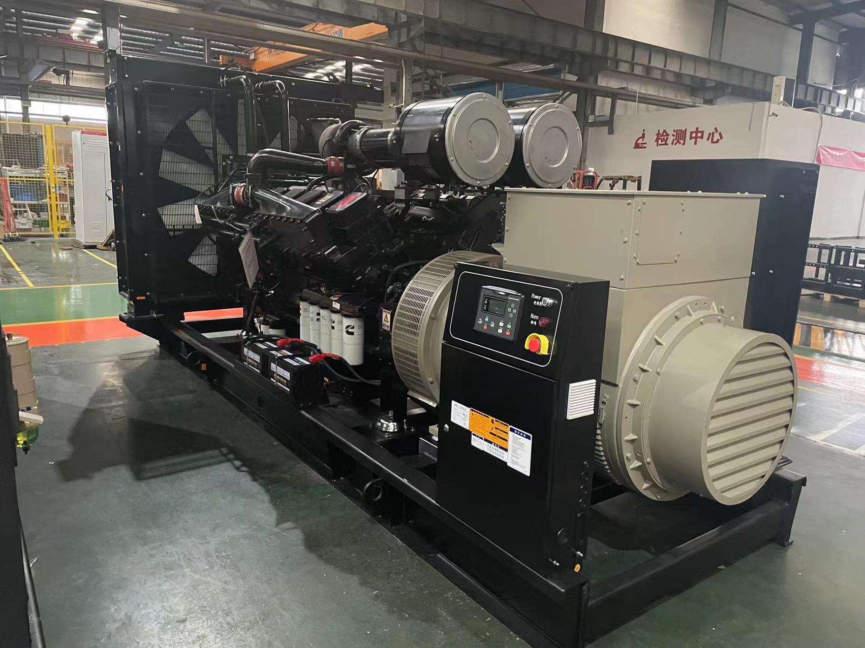
Residual magnetism is the small charge in the field iron that lets the buildup start, and it fades while a set sits. A generator excitation failure in cold sheds is usually this and nothing more, because a set that spends a winter unswitched loses the last trace of field and then refuses to build at the next start. The engine runs. The breaker closes. The voltmeter stays flat.
The reading that confirms it is tiny, often under 5V across the exciter stator on a frame that should show several times that. Tesla Power lists the expected residual figures by frame size in the fault-finding notes of the advice library, so the number has a reference before anyone replaces a part. Where the figure is missing, the cure is a field flash, which costs a battery and ten minutes rather than a regulator.
How do you test the exciter winding and the rotating diodes?
Rotating diodes fail more often than any other part in the chain, because they live on the rotor and take every load step. Isolate them with the set stopped and the end cover off. A healthy diode reads a forward drop between 0.4V and 0.6V one way, and an open reading the other way. A diode that conducts both ways is shorted. One that blocks both ways is open.
The exciter stator gets the same treatment with an insulation tester. Anything under 1 megohm to earth condemns the winding, and a figure near zero means the machine runs on borrowed time. Tesla Power ships the diode kit and the winding data sheet together for this reason, so the crew on site has the pass and fail figures beside the meter rather than in a file two time zones away.
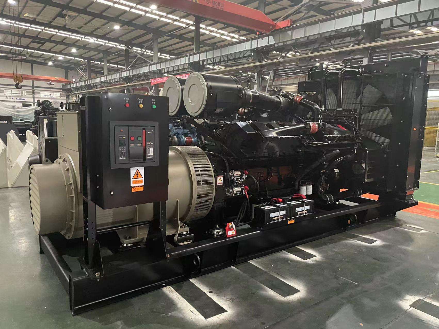
The same data sheet travels with the 1000kW container set built for industrial standby duty, and its alternator page carries the diode count and the torque figures the retest needs.
Is the fault in the AVR sensing circuit or the field supply?
Split the regulator into its two halves before condemning it. The sensing half watches the output terminals and compares the figure against an internal reference. The power half feeds the field. Feed a known reference into the sensing terminals from a battery and watch the output move. If the output follows the injected reference, the power half lives and the sensing input is the fault.
The pattern of a generator excitation failure for standby sets differs from a prime set in one respect: the regulator sits idle for months, so a dried capacitor or a corroded sensing terminal shows up at the first start rather than in service. The ISO 8528-1 steady-state voltage classes set the band the repaired set has to re-enter, and a load run proves it: a 500kVA frame at 0.8 power factor = 400kW, half load = 250kVA × 0.8 = 200kW, and a 100kVA load = 80kW, each point held for an hour while the volts stay inside the band. Tesla Power issues the load test sheet that records all three points.
How do you re-energise the field without damaging the AVR?
Field flashing works because a short burst of external current restores the residual the buildup needs. The safe routine is short and boring, which is the point. Stop the set. Disconnect the field leads from the regulator. Touch a 12V battery across the field for three to five seconds, correct polarity observed. Reconnect, start, and watch the voltmeter climb to its setting.
Where the buildup fails again within a week, the residual is not the fault at all, and the ladder moves back up to the diodes or the sensing circuit. The IEC 60034 series for rotating machines covers the winding tests that separate the two. Yangzhou Tesla Power writes the flash procedure and the field polarity into the commissioning file of every export order, because a reversed flash damages the regulator and turns a ten minute job into a parts order, and the works floor and its winding shop retests every returned regulator against that sequence.
What should the fault log tell the supplier?
Five lines turn a slow email exchange into a parts shipment. The set model and the alternator type. The symptom as observed, not as guessed. The three opening readings: residual voltage, field resistance, diode results. The hours on the counter and the storage history. The load, stated plainly, for example a 100kVA lighting board at 0.8 power factor = 80kW on the day the fault appeared. Chinese generator suppliers answer a log like that in one reply, because every figure maps to one component.
Two documents complete the file. A conformity assessment for the genset, kept from the original delivery, ties the serial number to the winding and diode data the factory built to. And the generator documentation for a warranty claim, which is the commissioning record plus this fault log, decides whether the repair lands on warranty or on the site budget. Two generator manufacturers in china quote the same parts differently once the evidence changes, and the log decides which quote is real. Tesla Power Equipment reads a five line log and replies with part numbers, so the service desk in Yangzhou can price the repair before the set leaves site.
Frequently asked questions about generator excitation failure
No. The engine keeps running and takes no harm from the loss of voltage, because the mechanical side is untouched. The risk sits elsewhere: loads that drop out, or a set that runs unmetered while the crew chases an electrical fault that was not there.
Open circuit asks nothing of the field, so a weak diode or a tired regulator can hold a no-load figure. Load steps demand real field current, and the weak link drops out. That is why the load run after repair matters as much as the no-load check.
Ten minutes including the restart, on most frames. The battery does the work, and no special tool is needed beyond a spanner for the field leads. If the flash has to be repeated weekly, stop flashing and test the diodes.
A both ways check on each diode with the rotor isolated. Forward drop of 0.4V to 0.6V one way and an open reading the other way is the pass. Any diode that fails the pair of readings is replaced as a set, not singly.
No, and fitting one blind wastes money. Roughly a third of the sets that arrive here with a replaced regulator had a sensing fault, a shorted diode or lost residual instead. The ladder exists so the regulator is the last part bought, not the first.
The five line log described above, plus a photograph of the regulator faceplate and the alternator plate. With that, our desk replies with the correct diode kit, regulator or winding service inside one working day, and the quotation lists the pass figures each part has to meet on retest.